Bearing Trivia
How to Select the Right Bearing (Part 2): How to decide the bearing arrangement
- #2 How to Select the Right Bearing
In Part 1, we explained how to select the type of bearing.
In Part 2, we will explain bearing arrangement as a measure for whether the bearing type you select is appropriate.
While we are on the subject, do you all know what "arrangement" means in this context? "Arrangement" means what kind of bearings, and how many of them, to put in place relative to the shaft.
In a standard machine, normally combining two (or more) bearings on a single shaft will provide additional load.
In Part 2, we will show you some of the representative examples of combining two bearings on a single shaft.
Table 1: Bearing selection checklist
| Order | Examination item | Major points to confirm |
|---|---|---|
| ① | Bearing type | What magnitude and direction of load do you need? Will it fit in the installation space? |
| ② | Bearing arrangement | Are you using two (or more) bearings on a single shaft? <This is the focus of Part 4> |
| ③ | Bearing dimensions and service life | Do the dimensions and service life satisfy your needs? |
| ④ | Bearing limiting speed, running accuracy, fits and internal clearance | Does it have the necessary running accuracy and rigidity for the machine? Does it have the fits and internal clearance to satisfy its service life? |
| ⑤ | Bearing preload and rigidity | Does it have the necessary rigidity for the machine? |
| ⑥ | Bearing lubrication | Can the bearing rotate stably over a long period of time? |
| ⑦ | Components around the bearing | What bearing surrounding structure/assembly are you looking for? |
| ⑧ | Bearing mounting and dismounting | Will it facilitate maintenance/inspection of the machine? |
1. Points to consider when determining the arrangement
There are two key points to decide on the arrangement of bearings.
- Thermal expansion should be considered
- In consideration of the applied load conditions, the fixed side and the free side should be separated
Now we will explain these two points.
2. Take thermal expansion into account when considering the arrangement
When a machine is operated and the bearings rotate, heat will be generated inside the bearings. This heat is transferred to surrounding components, causing the shaft and the housing to expand (see Figure 1).
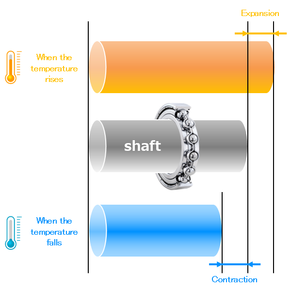
Fig. 1: Expansion and contraction of the shaft due to thermal expansion
3. Arranging bearings so the fixed side and free side are separate (preventing the shaft expansion/contraction)
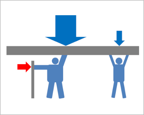
Bearings provide load by being inserted between the rotating and fixed parts of a machine.
From among two bearings on a single shaft, one is designated as the fixed side bearing, and it fixes the shaft and housing in the axial direction. This is called "locating." The other bearing is designated as the free side bearing, and it allows the shaft to move freely in the axial direction, preventing thermal expansion and contraction of the shaft.
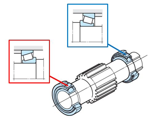
Fig. 2: The relationship between the visual sketch and the cross-section drawing
In this column we will be using cross-section drawing like the above to convey the contents like those shown in the visual sketch.
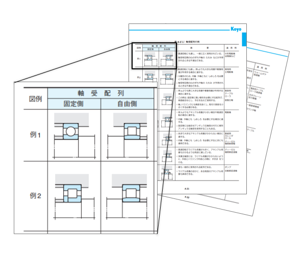
Fig. 3: Representative examples of bearing arrangement
Bearing arrangement and combination
1) Fixed side bearing
A radial load and an axial load are applied to the fixed side bearing in order to fix the shaft and housing in the axial direction. For this reason, you should select a type of bearing that can support both the radial and axial loads and that is appropriate to the magnitude of these loads.
Table 2: Types of bearing typically used on the fixed side
| Magnitude of load | Type of bearing |
|---|---|
| light | Deep groove ball bearing or angular contact ball bearing (matched pair or double-row) |
| heavy | Cylindrical roller bearing with rib, tapered roller bearing (matched pair or double-row), or spherical roller bearing |
It is also possible for separate fixed side bearings to support a radial load and an axial load, respectively.
As shown in Figure 4, there is also an arrangement in which a deep groove ball bearing supports the axial load, and a cylindrical roller bearing supports only the radial load, by providing a clearance between the outside diameter of the deep groove ball bearing and the bore diameter of the housing.
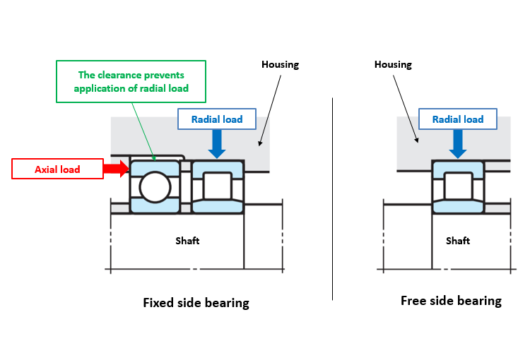
Fig. 4: Separate fixed side bearings supporting a radial load and an axial load, respectively
Which of the two bearings is used as the fixed bearing is determined by considering the balance of the machine structure and bearing service life.
As shown in Figure 5, the arrangement can also be such that the fixed side bearing is a large size of deep groove ball bearing that can support heavier radial load and axial load, while the free side bearing is a small size of deep groove ball bearing that supports only lighter radial load.
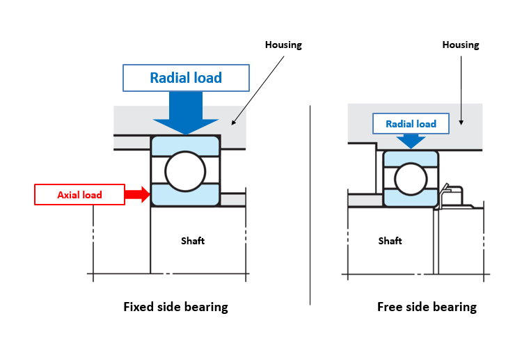
Fig. 5: A bearing arrangement that balances service life
We will explain in Part 3 about checking the service life of bearings.
2) Free side bearing
The free side bearing prevents thermal expansion and contraction of the shaft. In the case of a separable bearing (where the inner ring and outer ring can be separated), the expansion and contraction of the shaft is prevented between the rollers and the raceway surface.
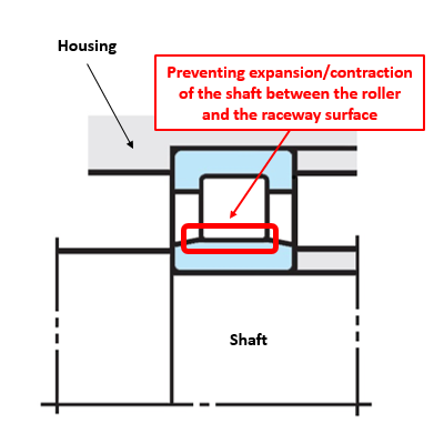
Fig. 6: A separable bearing (free side)
For non-separable bearings (where the inner ring and outer ring cannot be separated), a clearance is provided between the outer diameter of the bearing and the inner diameter of the housing to prevent the thermal expansion and contraction of both the shaft and the bearing.
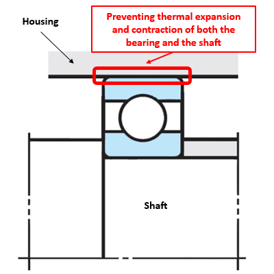
Fig. 7: A non-separable bearing (free side)
Table 3: Types of bearing typically used on the free side
| Type of bearing | |
|---|---|
| Separable | Cylindrical roller bearing (NU and N types), needle roller bearing (NA type) |
| Non-separable | Deep groove ball bearing, angular contact ball bearing (in combination or double-row), double-row tapered roller bearing, or spherical roller bearing |
3) Check for misalignment between the bearing's inner and outer rings
A large misalignment may occur between the inner and outer rings of the bearing due to load-induced shaft bending or mounting errors between the fixed side and free side bearings. If there is a large misalignment, an abnormal load will be put on the bearing, which can cause damage.
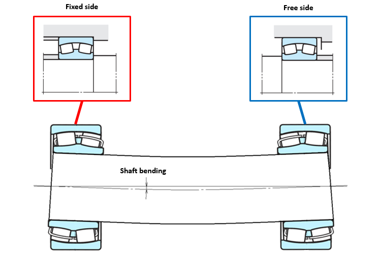
Fig. 8: Misalignment of the bearing's inner and outer rings
Check the bearing type according to the allowable misalignment angle of the bearing (see Table 4).
Table 4: Allowable misalignment angle of bearings
| Size of misalignment angle between inner ring and outer ring (taken from the Ball & Roller Bearings Catalog) Small ⇔ Large |
| Cylindrical roller bearings < Tapered roller bearings < Deep groove ball bearings, angular contact ball bearings < Spherical roller bearings, self-aligning ball bearings |
4. A bearing arrangement in which the fixed and free sides are not distinguished
There are also bearing arrangements in which the fixed and free sides are not distinguished.
1) Small machines with little effect from shaft expansion/contraction
Small machines that support small loads with short shafts are less affected by shaft expansion/contraction, so two bearings may be arranged without distinction between the fixed and free sides (see Figure 9).
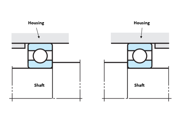
Fig. 9: The arrangement of bearings in a small machine
2) When giving rigidity to the shaft
When the preload is applied to enhance rigidity to the shaft, there is no distinction between the fixed side and free side bearings. (Preload will be introduced in detail in Part 3 and later.) In this case, two angular contact ball bearings or tapered roller bearings are mounted with a back-to-back or face-to-face arrangement. (See Figure 10.)
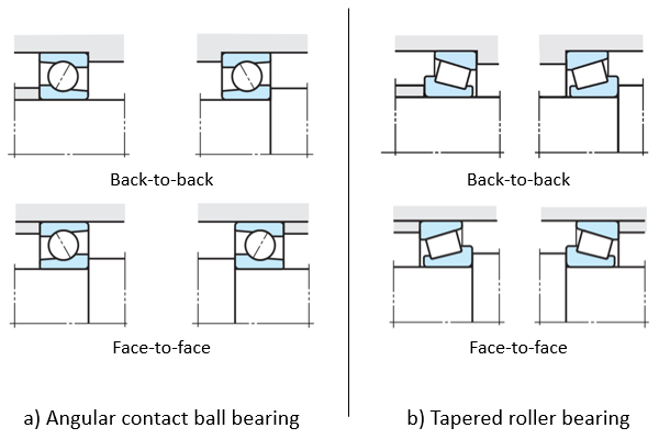
Fig. 10: Mounting method (mounted bearing)
Table 5 shows a comparison of face-to-face and back-to-back bearing arrangement.
When deciding between face-to-face or back-to-back bearing arrangement, it is necessary to take the "moment" into account.
The "moment" is obtained by multiplying the magnitude of applied load and the distance to the point where the load is applied, and either face-to-face or back-to-back bearing arrangement is selected according to this "magnitude of moment."
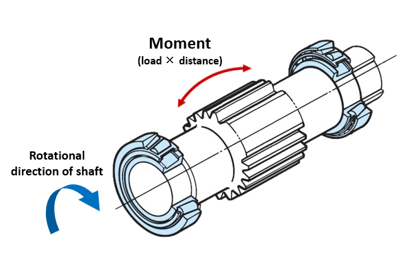
Fig. 11: Moment (face-to-face)
Table 5: Comparison of face-to-face and back-to-back bearing arrangements
| Face-to-face bearing arrangemnet | Back-to-back bearing arrangemnet | |
|---|---|---|
| Load center position (see Figure 12) | Short | Long |
| Relative to the moment | Weak (low rigidity) → If the moment is small |
Strong (high rigidity) → If the moment is large |
| Bearing mounting | Clamp the outer ring | Clamp the inner ring |
As indicated in Table 5, select face-to-face bearing arrangement when the moment is small, and back-to-back bearing arrangement when the moment is large.
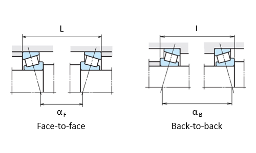
Fig. 12: Load center position (αF < αB)
5. Conclusion
We explained how to decide on the bearing arrangement in order to determine whether the bearing type you chose was appropriate.
- Select a free side bearing to prevent expansion and contraction of the shaft due to thermal expansion.
- Select a bearing with an allowable misalignment angle.
- When giving preload to make the shaft rigid, it is not necessary to distinguish bearings for fixed and free sides, but use two angular contact ball bearings or tapered roller bearings that are arranged face-to-face or back-to-back with each other.