Bearing Trivia
Drive Shafts for Steel Production/Industrial Equipment -- Introduction, Inspections and Cases of Failures
- JTEKT Product Courses
Many types of bearings and oil seals are used in rotating machines.
Cases of bearing and oil seal failures are introduced at the end of this column. Please refer to these as necessary.
JTEKT manufactures and sells drive shafts for transmitting power to steel production and industrial equipment.
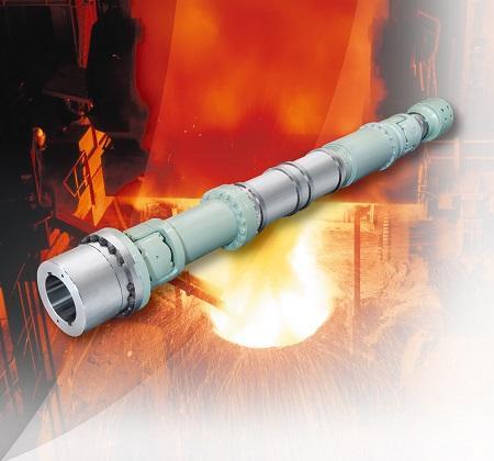
Although JTEKT's catalog, Drive shafts for steel production / industrial equipment, includes information on drive shafts for steel production and industrial equipment, the many technical terms used in the catalog may prevent some people from taking the time to read it.
For that reason, this column uses drive shafts for steel production as an example for introducing readers to drive shafts, their inspections, and cases of failure.
[Drive shafts for steel production / industrial equipment catalog]
1. What is a drive shaft?
A drive shaft is a revolving shaft used to transmit the power of a motor to a machine.
Drive shafts are generally installed in the limited space inside a machine.
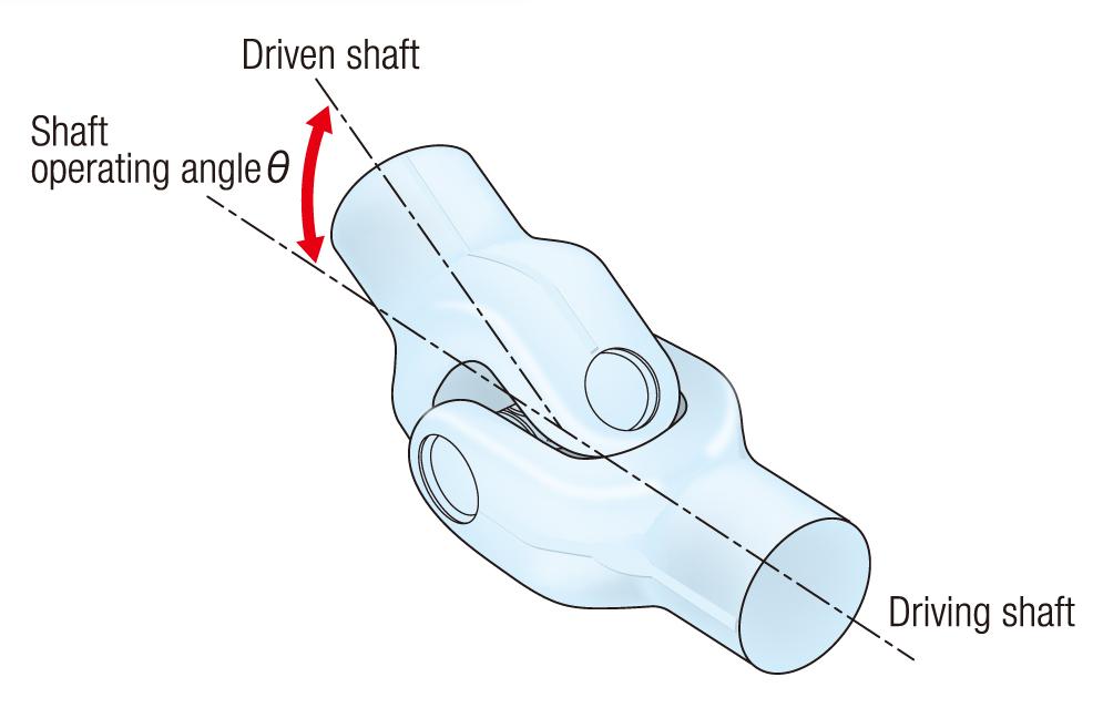
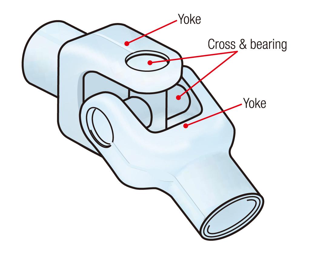
To flexibly connect the driving shaft (input axis) and the driven shaft (output axis) within this limited space and enable smooth power transmission from a motor, drive shafts have universal joints (also called "cross-type universal joints") as shown in Figure 1.
 |
 |
| a) Connection of driving shaft and driven shaft | b) Structure |
Figure 1: Universal joint
Each universal joint uses a cross & bearing consisting of four rolling bearings (see Figure 2), realizing low friction and minimizing torque losses.
Figure 2: Cross & bearing structure
2. Drive shaft parts
Figure 3 shows a typical example of a drive shaft used in a rolling mill while Table 1 presents explanations of the drive shaft components.
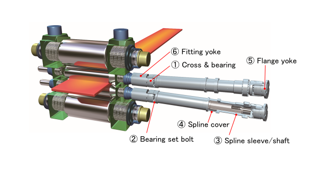
Figure 3: Drive shaft for rolling mill
Table 1: Drive shaft components
| 番号 | 部品名称 | 説明 |
| ① | Cross & bearing | Consists of a cross-shaped shaft and four rolling bearings that individually support each shaft. |
| ② | Bearing set bolt | Used to connect the cross & bearing and its mating part. |
| ③ | Spline sleeve/shaft | There are a spline hole and shaft and the attaching length is adjustable. |
| ④ | Spline cover | Used to improve the dustproof and waterproof properties of the spline. |
| ⑤ | Flange yoke | Used mainly for connection with a drive unit. Various types of coupling arrangements are provided according to the application. |
| ⑥ | Fitting yoke | Used mainly for connection with the machine and the motor. Various types of coupling arrangements are provided according to the application. |
Drive shaft types are classified according to the structure of the cross & bearings. Table 2 shows one of the drive shaft type and its features.
Table 2: Drive shaft type and features
| Type | Features | Representative structure |
| Block type | Intended for use in extremely heavy-duty applications under severe operating conditions subject to water and dust. | Figure 4 |
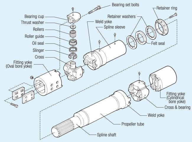 Figure 4: Block type
3. Selecting a drive shaft
A drive shaft should be selected to satisfy the required (1) strength, (2) service life, (3) operating angle (see Figure 1), and (4) dimensions according to the purpose of the machine.
See the following for details on selecting a drive shaft.
["Drive shaft selection" in the Drive shafts for steel production / industrial equipment catalog]
4. Maintenance and inspection method of drive shaft
To use drive shafts safely for a long time, periodic inspection is required.
1) Periodic inspection
Periodic inspections include greasing and the tightening torque of cross & bearing set bolts.
A) Greasing
Apply grease of the same brand to the (1) cross & bearing and (2) spline part shown in Figure 5 while observing the greasing intervals (see Table 3) and amounts. Contact JTEKT for information regarding greasing amounts and grease brands.
|
N.B. |
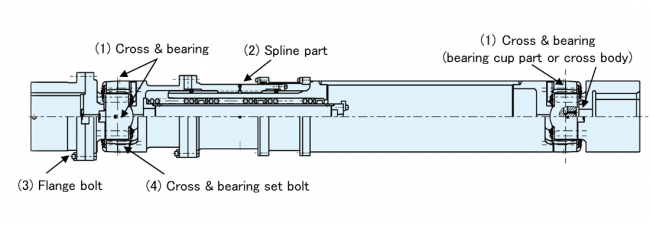 Figure 5: Greasing positions
Table 3: Cycles of periodic greasing
| Equipment | Cycles of periodic greasing |
| Hot strip mills | Once a month |
| Cold strip mills | Once a month |
| そOther equipment | Every 3 months |
B) Inspection of tightening torque
Perform inspections of bearing set bolts (bolts for setting the cross & bearing and flange bolts) according to the cycles shown in Table 4.
Table 4: Inspection of bearing set bolts
| Equipment | Inspection cycle |
| Initial inspection | 1 week and 1 month after operation |
| Periodic inspection | Every 6 months |
Inspection of the bearing set bolts includes the following.
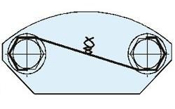
• Check for looseness of the bearing set bolts or damage of the whirl-stop (see Figure 6)
 |
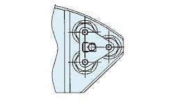 |
| a) Whirl-stop with one bolt | b) Whirl-stop with three bolts |
Figure 6: Whirl-stop of bearing set bolts
• Check for bearing set bolt elongation by hammering or visual inspection (see Figure 7)
Figure 7: Check for elongation of the bearing set bolt
Loosen or tighten bearing set bolts using the following procedure.
• Tighten the drive shaft with a jig such as chain tongs (see Figure 8).
• Before tightening the bearing set bolt, apply a small amount of grease to the thread section and the head seat of the bolt.
• Tighten the bearing set bolt to the specified torque using a wrench, tensiometer, etc. (see Figure 8).
|
N.B. |
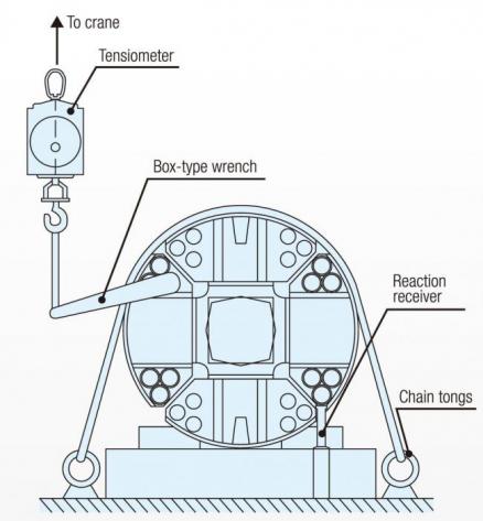
Figure 8: How to tighten the drive shaft
2) Overhaul
To prevent long-term equipment stoppages and serious accidents, an overhaul of the major parts of rolling mill drive shafts (see Figures 9 and 10) is performed approximately once a year after the start of operation.
Table 5 shows checks to be performed during the overhaul.
Figure 9: Major parts that are overhauled
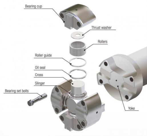
Figure 10: Major parts of cross & bearings (cross & bearing, bearing set bolts, yoke)
Table 5: Overhaul of major parts
| Part | Inspected location | Check for damage |
| Cross of cross & bearing | Brinelling, wear, flaking, seizure, cracks, nicks, or rusting, etc. | |
| Bearing cup of cross & bearing | ||
| Bearing set bolt | Bolt bending, elongation, cracks, or rusting, etc. | |
| Yoke | Cracks, nicks, or rusting, etc. (especially the cross & bearing attaching part and flange attaching part) | |
| Fitting yoke (Oval bore yoke) |
Wear, scuffing, cracks, etc. | |
|
Spline sleeve/shaft |
See the following for details on maintenance and inspection method of the drive shaft.
3) Cases of drive shaft failures
Tables 6 to 10 and Figures 12 to 20 show cases of failures, causes, and countermeasures for each major part of the drive shaft.
The appropriate countermeasures must be taken if a failure is discovered.
Table 6: Cases of cross & bearing failures
| Part | Cases of failures | Figure | Cause | Countermeasure |
| Cross of cross & bearing | Flaking at bottom of raceway surface |
Figure 11 |
• Insufficient lubrication | • Periodic greasing |
| Flaking at end of raceway surface | Figure 12 | • Material fatigue due to long-term use | • Application of different diameter rollers See Figure 13. |
|
| Brinelling of raceway surface | Figure 14 | • Excessive load | • Review the usage conditions • Apply an appropriate load |
|
| Bearing cup of cross & bearing | Flaking of raceway surface | Figure 15 | • Insufficient lubrication | • Periodic greasing |
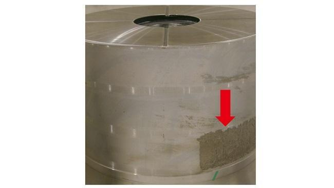
Figure 11: Flaking at bottom of cross raceway surface
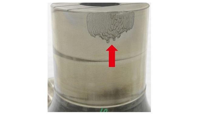
Figure 12: Flaking at end of cross raceway surface
Figure 13: Equal loads due to application of different diameter rollers
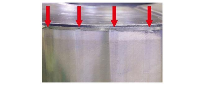
Figure 14: Brinelling of cross raceway surface
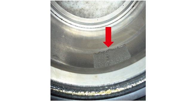
Figure 15: Flaking of bearing cup raceway surface
Table 7: Cases of bearing set bolt failures
| Part | Case of failure | Figure | Cause | Countermeasure |
| Bearing set bolt | Breakage of bolt (flat fracture shape) |
Figure 16 | • Axial force did not act on the bolt | • Tighten with the specified tightening torque • Maintenance of the attaching surfaces of the bearing cup and yoke |
| Breakage of bolt | Figure 17 | • Application of excessive bending stress | • Review the usage conditions • Apply an appropriate load • Reduce the bending stress |
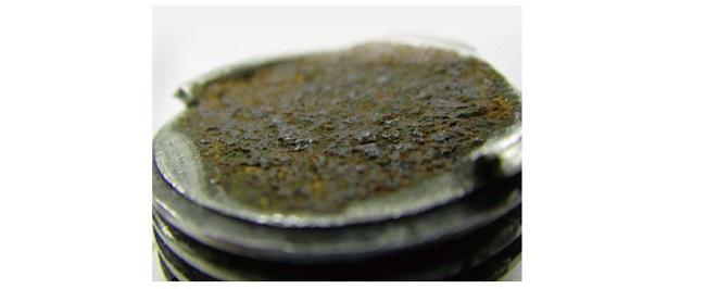
Figure 16: Breakage of bearing set bolt (flat fracture shape)
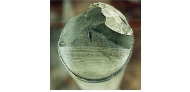
Figure 17: Breakage of bearing set bolt
Table 8: Cases of yoke failures
| Part | Case of failure | Figure | Cause | Countermeasure |
| Yoke | Dent deformation of keyway | Figure 18 | • Excessive load | • Review the usage conditions • Apply an appropriate load |
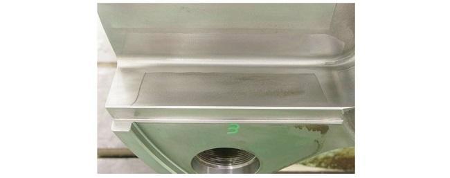
Figure 18: Dent deformation of yoke keyway
Table 9: Cases of fitting yoke (oval bore yoke) failures
| Part | Case of failure | Figure | Cause | Countermeasure |
| Fitting yoke (oval bore yoke) |
Wear of oval bore |
Figure 19 |
• Wear of oval bore inlet and interior • Excessive clearance due to corrosion and wear of the torque transmission surface • Wear of the torque transmission surface due to long-term use |
Hardening of contact surface Repair by overlay welding |
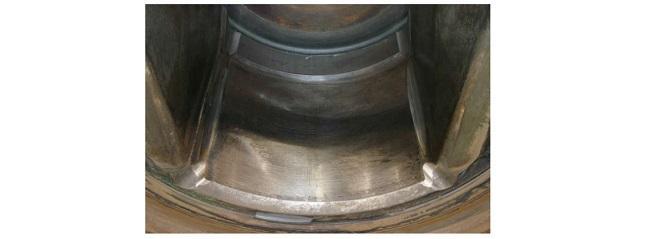
Figure 19: Wear of fitting yoke (oval bore yoke)
Table 10: Cases of spline failures
| Part | Case of failure | Figure | Cause | Countermeasure |
| Spline sleeve/shaft | Wear of spline part | Figure 20 | • Wear of the torque transmission surface due to long-term use |
Reusable in the case of slight wear Replace with a new part in the case of serious wear |
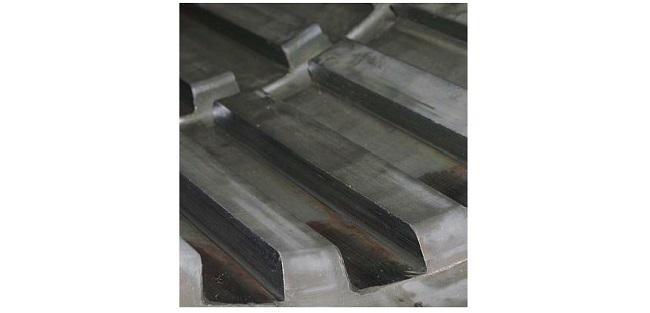
Figure 20: Wear of spline part of spline sleeve
See the following for details on cases of drive shaft failures.
["Cases of failures" in the Drive shafts for steel production / industrial equipment catalog]
Also, feel free to contact JTEKT regarding inspections and repairs for large size drive shafts.
5. Conclusion
This column introduced readers to drive shafts for steel production/industrial equipment, their inspections, and cases of failure.
| 1) | A universal joint (cross-type universal joint) is used for the drive shaft to enable smooth power transmission from a motor to a machine. |
| 2) | To use drive shafts safely for a long time, periodic inspection is required. Periodic inspections include greasing and the tightening torque of cross & bearing set bolts. Please perform these inspections as recommended by JTEKT. |
| 3) | Overhaul of major parts is performed on drive shafts for steel production equipment. Perform the appropriate countermeasures for failures found during overhauls in order to prevent equipment stoppages and serious accidents. |
| 4) | Also see the cases of bearing and oil seal failures. Bearing Failure (Part 1): "Failure" and "damage" |
If you have any technical questions regarding drive shafts for steel production/industrial equipment, or opinions/thoughts on these "Bearing Trivia" pages, please feel free to contact us using the following form.
