As bearing operational conditions vary depending on devices in which bearings are mounted, different performances are demanded of bearings. Normally, two or more bearings are used on one shaft.
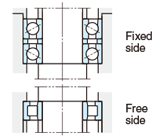
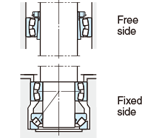
In many cases, in order to locate shaft positions in the axial direction, one bearing is mounted on the fixed side first, then the other bearing is mounted on the free side.
Table 4-1 Bearings on fixed and free sides
Features
Recommended bearing type
Example No.
Fixed side bearing
This bearing determines shaft axial position.
This bearing can accommodate both radial and axial loads.
Since axial load in both directions is imposed on this bearing, strength must be considered in selecting the bearing for this side.
Deep groove ball bearing Matched pair or stack angular contact ball bearing Double-row angular contact ball bearing Self-aligning ball bearing Cylindrical roller bearing with rib (NUP and NH types) Double-row tapered roller bearing Spherical roller bearing
Examples 1−11
Free side bearing
This bearing is employed to compensate for expansion or shrinkage caused by operating temperature change and to allow ajustment of bearing position.
Bearings which accommodate radial load only and whose inner and outer rings are separable are recommended as free side bearings.
In general, if non-separable bearings are used on free side, clearance fit is provided between outer ring and housing to compensate for shaft movement through bearings. In some cases, clearance fit between shaft and inner ring is utilized.
Separable types Cylindrical roller bearing (NU and N types) Needle roller bearing (NA type, etc.)
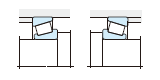
When bearing intervals are short and shaft shrinkage does not greatly affect bearing operation, a pair of angular contact ball bearings or tapered roller bearings is used in paired mounting to accommodate axial load.
After mounting, the axial clearance is adjusted using nuts or shims.
*Bearings which can accommodate both radial and axial loads should be used on fixed side. Heavy axial load can be accommodated using thrust bearings together with radial bearings.
Bearings which can accommodate radial load only are used on free side, compensating for shaft movement.
This is optimum arrangement for applications with possible mounting errors or shaft deflection.
Ease of mounting and dismounting, ensured by use of adaptor, makes this arrangement suitable for long shafts which are neither stepped nor threaded.
This arrangement is not recommended for applications requiring axial load capability.
General industrial equipment counter shafts
Ex. 11
This is the optimum arrangement for applications with possible mounting errors or shaft deflection.
)This is recommended for operations under impact load or radial load heavier than that in Ex. 10.
This arrangement can accommodate partial axial load as well as radial load.
Steel manufacturing table rollers
Example
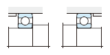
Arrangement in which fixed and free sides are not distinguished
Recommended application
Application example
Ex. 12
This arrangement is most popular when applied to small equipment operating under light load.
When used with light preloading, thicknessadjusted shim or spring is mounted on one side of outer ring.
Small motors, small speed reducers, small pumps
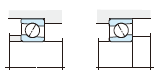
Ex. 13
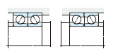
Back-to-back
Face-to-face
This is suitable for applications in which rigidity is enhanced by preloading. This is frequently employed in applications requiring high speed operation under relatively large axial load.
Back-to-back arrangement is suitable for applications in which moment load affects operation.
When preloading is required, care should be taken in preload adjustment.
Machine tool spindles
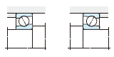
Ex. 14
Back-to-back
Face-to-face
This is recommended for operation under impact load or axial load heavier than in Ex. 13.
This is suitable for applications in which rigidity is enhanced by preloading.
Back-to-back arrangement is suitable for applications in which moment load affects operation.
When interference is required between inner ring and shaft, face-to-face arrangement simplifies mounting. This arrangement is effective for applications in which mounting error is possible.
When preloading is required, care should be taken in preload adjustment.
Speed reducers, automobile wheels
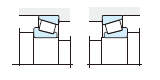
Ex. 15
This is recommended for applications requiring high speed and high accuracy of rotation under light load.
This is suitable for applications in which rigidity is enhanced by preloading.
Tandem arrangement and face-to-face arrangement are possible, as is back-to-back arrangement.
Machine tool spindles
Ex. 16
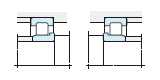
This arrangement provides resistance against heavy radial and impact loads.
This is applicable when both inner and outer rings require interference.
Care should be taken not to reduce axial internal clearance a critical amount during operation.
Construction equipment final drive
Example
Application to vertical shafts
Recommended application
Application example
Ex. 17
This arrangement, using matched pair angular contact ball bearings on the fixed side and cylindrical roller bearings on the free side, is suitable for high speed operation.
Vertical motors, vertical pumps
Ex. 18
This is recommended for operation at low speed and heavy load, in which axial load is heavier than radial load.
Due to self-aligning capability, this is suitable for applications in which shaft runout or deflection occurs.
Crane center shafts, vertical pumps
Still having trouble
Please feel free to contact Us by phone and/or e-mail.