Bearing Trivia
How to Select the Right Bearing (Part 7): Components surrounding the bearing
- #2 How to Select the Right Bearing
In Part 6, we explained about bearing lubrication.
A list of earlier "How to Select the Right Bearing" entries can be seen here.
In Part 7, we will explain about points you need to consider regarding the components surrounding the bearing.

Table 1 shows the bearing selection checklist.
In order to ensure the intended performance of the machine, it is important to lay out the components surrounding the bearing in accordance with the usage conditions.
It is also, of course, necessary to consider the cost performance of maintenance and inspection with mounting and dismounting.
Table 1: Bearing selection checklist
| Order | Examination item | Major points to confirm |
|---|---|---|
| ① | Bearing type | What magnitude and direction of load do you need? Will it fit in the installation space? |
| ② | Bearing arrangement | Are you using two (or more) bearings on a single shaft? |
| ③ | Bearing dimensions and service life | Do the dimensions and service life satisfy your needs? |
| ④ | Bearing limiting speed, running accuracy, fits and internal clearance | Does it have the necessary running accuracy and rigidity for the machine? Does it have the fits and internal clearance to satisfy its service life? |
| ⑤ | Bearing preload and rigidity | Does it have the necessary rigidity for the machine? |
| ⑥ | Bearing lubrication | Can the bearing rotate stably over a long period of time? |
| ⑦ | Components around the bearing | What bearing surrounding structure/assembly are you looking for? <This is the focus of Part 7> |
| ⑧ | Bearing mounting and dismounting | Will it facilitate maintenance/inspection of the machine? |
This Bearing Trivia entry explains the following points with regard to the components surrounding the bearing.
- The design (including accuracy and roughness) of the shaft and housing
- Bearing mounting dimensions
- Sealing devices
1. The design of the shaft and housing
Table 2 introduces the points to be aware of in the design of the shaft and housing.
Note that it is necessary to perform the design from a comprehensive perspective, also taking cost performance into account.
Table 2: Points to be aware of in the design of the shaft and housing
| No. | Examination contents | Points to be aware of |
|---|---|---|
| 1 | Shape and dimensions of the shaft | Reduce distortion and bending |
| 2 | Shape and dimensions of the housing | Reduce distortion |
| 3 | Roughness of the fitting surfaces of the shaft and housing | Appropriate accuracy and roughness |
| 4 | The fillet radius of the shaft and housing | Smaller than the chamfer dimension of the bearing |
| 5 | The shoulder heights of the shaft and housing | Support applied force and make the bearing easy to dismount |
| 6 | Locknuts and screw threads for shaft mounting | Appropriate perpendicularity |
| 7 | Split housings | Shape and roughness of the meeting surfaces |
1) Shape and dimensions of the shaft
A shaft should be designed as thick and short as possible, so that the force applied to the shaft during operation does not result in significant distortion and bending that would decrease the service life of the bearing. If there is limited installation space in the radial direction, it is also effective to select a double-row bearing or a wider bearing from width series 2 or higher.
For more details, see:
2) Shape and dimensions of the housing
A housing with rigidity should be designed, so that the force applied to the housing during operation does not result in significant distortion of the housing that would decrease the service life of the bearing. With housings made of aluminum or another light alloy, rigidity can be provided by inserting a steel bushing (see Figure 1).
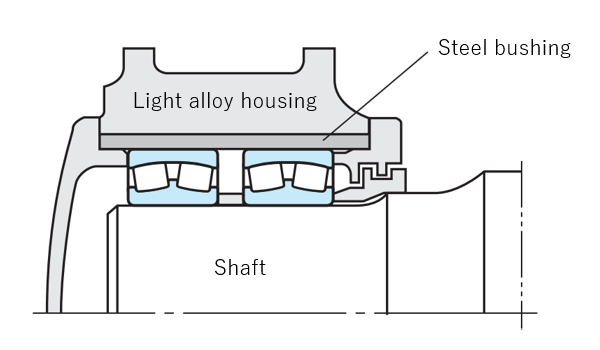 Fig. 1: Example of light alloy housing
<N.B.>
The expansion coefficient of a light alloy housing greatly differs from that of the bearing, so care needs to be taken when selecting the fit.
3) Fitting surfaces of the shaft and housing
The fitting surfaces of the shaft and housing should be finished in order to acquire the required accuracy and roughness (see Table 3).
The shoulder end-face should be finished in order to be perpendicular to the shaft center or housing bore surface.
Under general operating conditions, the fitting surface is finished by turning. However, if the conditions require minimal vibration and noise, or if the bearing is used under severe operating conditions, a ground finish is required.
Table 3: Accuracy and roughness of shafts and housings (recommended)
| Item | Bearing class | Shaft * | Housing * |
|---|---|---|---|
| Roundness tolerance | Class 0, class 6 | IT 3 ~ IT 4 | IT 4 ~ IT 5 |
| Class 5, class 4 | IT 2 ~ IT 3 | IT 2 ~ IT 3 | |
| Cylindrical form tolerance | Class 0, class 6 | IT 3 ~ IT 4 | IT 4 ~ IT 5 |
| Class 5, class 4 | IT 2 ~ IT 3 | IT 2 ~ IT 3 | |
| Shoulder runout tolerance | Class 0, class 6 | IT 3 | IT 3 ~ IT 4 |
| Class 5, class 4 | IT 3 | IT 3 | |
| Roughness of the fitting surfaces Ra (μm) | Small size bearings |
0.8 | 1.6 |
| Large bearings |
1.6 | 3.2 |
[Remarks]
* Refer to the figures listed in the following when the basic tolerance IT is required:
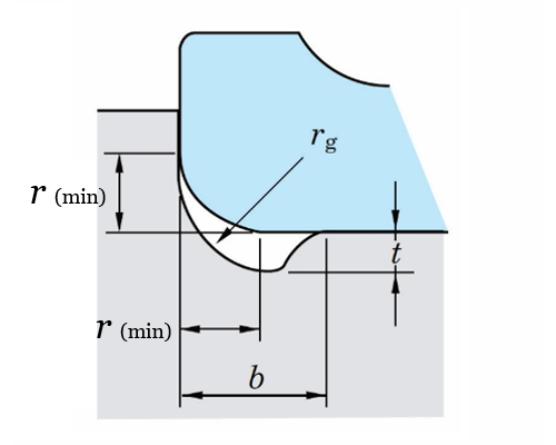
4) The fillet radius of the shaft and housing
The fillet radius (ra) of the shaft/housing should be smaller than the chamfer dimension of the bearing. Generally, it should be a simple circular arc, but, when the shaft is given a ground finish, a recess (grinding undercut) may be provided (see Figure 2).
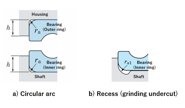 Fig. 2: Fillet radius
If the fillet radius must be larger than the bearing chamfer (ra2 > ra), a spacer should be inserted between the inner ring and shaft shoulder, or between the outer ring and housing shoulder (see Figure 3).
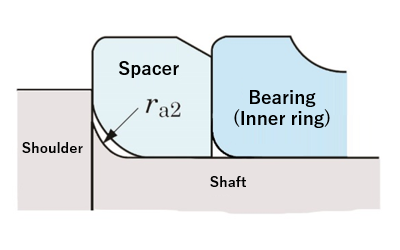 Fig. 3: Example of spacer inserted between bearing inner ring and shaft shoulder
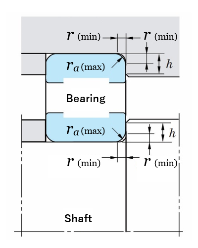
5) The shoulder heights of the shaft and housing
The shoulder height (h) of the shaft and housing should be decided so as to make the bearing easy to dismount. The shoulder diameter of the shaft should be smaller than the outside diameter of the inner ring, while the shoulder diameter of the housing should be larger than the inside diameter of the outer ring (see Figure 4).
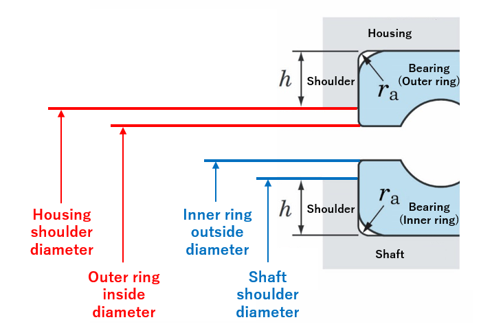 Fig. 4: Shoulder heights of shaft and housing
6) Locknuts and screw threads for shaft mounting
If applying an axial load or preload, locknuts or screw threads are attached to the shaft. These nuts/screws are set to be as perpendicular to the shaft axis as possible (see Figures 5 and 6).
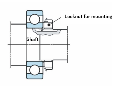 Fig. 5: Shaft locknut for mounting
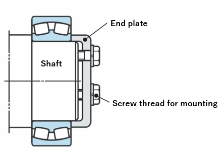 Fig. 6: Screw thread for mounting (attach the end plate)
7) Split housings
In a split housing, machine a recess on the bore surface where housings meet and finish the meeting surfaces smoothly, and then assemble the housings together (see Figure 7).
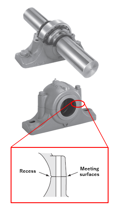 Fig. 7: Recess on bore surface area meeting surfaces of split housing
2. Bearing mounting dimensions
The "mounting dimensions" of a bearing are the dimensions necessary to mount the bearing. The mounting dimensions are the fillet radius and shoulder diameter of the shaft and housing.
Based on the standard values indicated in Table 4, our catalog lists the mounting dimensions for each bearing number (see Table 5). Additionally, the grinding undercut dimensions for ground shafts are given in Table 6.
Table 4: Shaft/housing fillet radius and shoulder height of radial bearings (excerpt)
Unit: mm
| Chamfer dimension of inner ring or outer ring r(min) |
Shaft and housing | |
|---|---|---|
| Fillet radius ra(max) | Shoulder height h(min) General cases |
|
| 0.3 | 0.3 | 1.25 |
| 1 | 1 | 2.75 |
| 1.5 | 1.5 | 4.25 |
Table 5: Mounting dimensions by bearing number (example; deep groove ball bearings; excerpt)
| Bearing number | Mounting dimensions(mm)* | ||
|---|---|---|---|
| da(min) | Da(max) | ra(max) | |
| 6906 | 32 | 45 | 0.3 |
| 6006 | 35 | 50 | 1 |
| 6206 | 35 | 57 | 1 |
| 6406 | 38 | 82 | 1.5 |
[Remarks]
* See Figure 8 for the meanings of the symbols used for mounting dimensions.
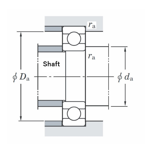 Fig. 8: Mounting dimensions of deep groove ball bearing
Table 6: Grinding undercut dimensions for ground shafts (excerpt)
| Chamfer dimension of inner ring r(min) |
Grinding undercut dimensions | ||
|---|---|---|---|
| t | rg | b | |
| 1 | 0.2 | 1.3 | 2 |
| 1.1 | 0.3 | 1.5 | 2.4 |
| 1.5 | 0.4 | 2 | 3.2 |
3.Sealing devices
Sealing devices for bearings not only prevent foreign matter (dirt, water, metal powder) from entering, but prevent lubricant inside from leaking, preventing damage to the bearing itself. It is necessary to consider which is the most suitable sealing device as well as the proper lubricating method for your bearings' operating condition
Sealing devices come in two types: non-contact and contact.
1) Non-contact type sealing devices
Non-contact type sealing devices, which eliminate friction because they do not have a contact point with the shaft, are especially suitable for operation at high rotation speed and high temperature.
There are three varieties of non-contact type sealing devices: oil groove, flinger (also called slinger), and labyrinth.
a) Oil groove
This kind of sealing device has three or more grooves at the narrow clearance between the shaft and housing cover.
Except when used with grease lubrication at low rotation speed, it is usually accompanied by other sealing devices.
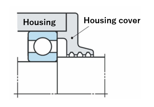 Fig. 9: Example of oil groove structure
b) Flinger (slinger)
Flingers utilize centrifugal force to splash away oil and dirt. They produce an air stream which prevents oil leakage and dirt by a pumping action.
They are very often used together with other sealing devices.
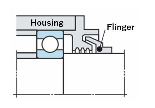 Fig. 10: Example of flinger (slinger) structure
c) Labyrinth
Labyrinths provide clearance in the shape of engagements between the shaft and housing.
They especially prevent lubricant leakage at high rotation speed.
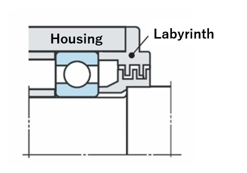 Fig. 11: Example of labyrinth structure
2) Contact type sealing devices
Contact type sealing devices provide a sealing effect by means of contact between their end and the shaft, and are manufactured from substances such as synthetic rubber or synthetic resin. Synthetic rubber oil seals are the most popular.
Figure 12 shows an example of an oil seal structure.
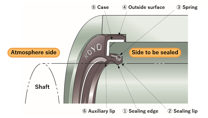
| No. | Names | Functions |
|---|---|---|
| ① | Sealing edge | Prevents fluid leakage by coming in contact with the rotating shaft |
| ② | Sealing lip | Provides proper pressure on the sealing edge to maintain stable contact |
| ③ | Spring | Raises pressure on the sealing lip and maintains such pressure |
| ④ | Outside surface | Fixes the oil seal to the housing and prevents fluid leakage through the fitting surface |
| ⑤ | Sealing edge | Strengthens the oil seal |
| ⑥ | Auxiliary lip | Prevents entry of contaminants |
Fig. 12: Example of oil seal structure and functions
JTEKT sells various types of oil seals.
Product Information: Oil Seals
Conclusion
In order to ensure the intended performance of the machine, it is important to lay out the components surrounding the bearing in accordance with the usage conditions.
It is also, of course, necessary to consider the cost performance of maintenance and inspection with mounting and dismounting.
- The shaft and housing should be designed so as to prevent significant distortion and bending of the shaft and housing due to the force applied during operation. The fitting surfaces of the shaft and housing should also be finished in order to acquire the required accuracy and roughness. If the conditions require minimum vibration and noise, or if the bearing is used under severe operating conditions, a ground finish is required.
- Bearing mounting dimensions are determined based on the recommended dimensions for the bearing number of the selected bearing.
- There are two types of sealing devices: non-contact and contact. The type best-suited for the operating condition should be selected.