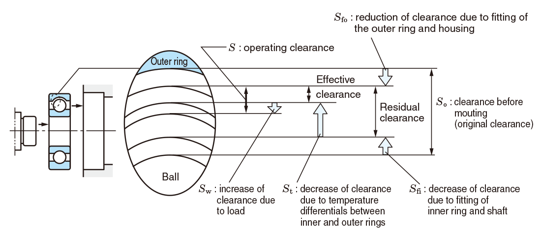
Table 10-1 shows how to determine the operating clearance when the shaft and housing are made of steel.
『Table 10-1 How to determine operating clearance』
Tables 10-2 to 10-10 show standard values for bearing internal clearance before mounting.
『Table 10-2 Radial internal clearance of deep groove ball bearings (cylindrical bore)』
『Table 10-3 Radial internal clearance of extra-small/miniature ball bearings』
『Table 10-4 Axial internal clearance of matched pair angular contact ball bearings (measurement clearance)』
『Table 10-5 Radial internal clearance of double-row angular contact ball bearings』
『Table 10-6 Radial internal clearance of self-aligning ball bearings』
『Table 10-7 Radial internal clearance of electric motor bearings』
『Table 10-8 Radial internal clearance of cylindrical roller bearings and machined ring needle roller bearings』
『Table 10-9 Radial internal clearance of spherical roller bearings』
『Table 10-10 Radial internal clearance of double/four-row and matched pair tapered roller bearings (cylindrical bore)』
Table 10-11 shows examples of clearance selection excluding CN clearance.
『Table 10-11 Examples of non-standard clearance selection』
Table 10-1 How to determine operating clearance
| Operating clearance(S) | S=So-(Sf+St1+St2)+Sw※ ※Sw (increase of clearance due to load) is generally small, and thus may be ignored, although there is an equation for determining the value. |
|
|---|---|---|
| Decrease of clearance due to fitting(Sf) |
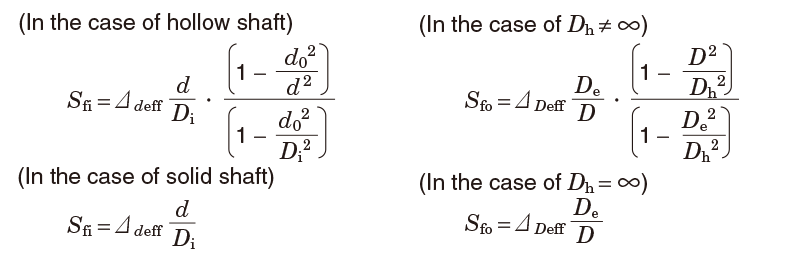 |
|
| Decrease of clearance due to temperature differentials between inner and outer rings(St1) | The amount of decrease varies depending on the state of housing; however, generally the amount can be approximated by the following equation on the assumption that the outer ring will not expand : St1=α(Di・ti-De・te) |
where :De=Di+2Dw Consequently,St1+St2will be determined by the following equation : St1+St2=α・Di・t1+2α・Dw・t2 (Temperature differential between the inner and outer rings, t1, can be expressed as follows : t1=ti-te Temperature differential between the rolling element and outer ring, t2, can be expressed as follows : t2=tw-te) |
| Decrease of clearance due to temperature rise of rolling element(St2) | St2=2α・Dw・tw | |
In Table 10-1,

- Bearings are sometimes used with a non-steel shaft or housing.
In the automotive industry, a statistical method is often incorporated for selection of clearance. In these cases, or when other special operating conditions are involved, JTEKT should be consulted.
Table 10-2 Radial internal clearance of deep groove ball bearings (cylindrical bore)
| Nominal bore diameter d,mm |
Clearance | ||||||||||
|---|---|---|---|---|---|---|---|---|---|---|---|
| C 2 | C N | C 3 | C 4 | C 5 | |||||||
| over | up to | min. | max. | min. | max. | min. | max. | min. | max. | min. | max. |
| 2.5 | 6 | 0 | 7 | 2 | 13 | 8 | 23 | 14 | 29 | 20 | 37 |
| 6 | 10 | 0 | 7 | 2 | 13 | 8 | 23 | 14 | 29 | 20 | 37 |
| 10 | 18 | 0 | 9 | 3 | 18 | 11 | 25 | 18 | 33 | 25 | 45 |
| 18 | 24 | 0 | 10 | 5 | 20 | 13 | 28 | 20 | 36 | 28 | 48 |
| 24 | 30 | 1 | 11 | 5 | 20 | 13 | 28 | 23 | 41 | 30 | 53 |
| 30 | 40 | 1 | 11 | 6 | 20 | 15 | 33 | 28 | 46 | 40 | 64 |
| 40 | 50 | 1 | 11 | 6 | 23 | 18 | 36 | 30 | 51 | 45 | 73 |
| 50 | 65 | 1 | 15 | 8 | 28 | 23 | 43 | 38 | 61 | 55 | 90 |
| 65 | 80 | 1 | 15 | 10 | 30 | 25 | 51 | 46 | 71 | 65 | 105 |
| 80 | 100 | 1 | 18 | 12 | 36 | 30 | 58 | 53 | 84 | 75 | 120 |
| 100 | 120 | 2 | 20 | 15 | 41 | 36 | 66 | 61 | 97 | 90 | 140 |
| 120 | 140 | 2 | 23 | 18 | 48 | 41 | 81 | 71 | 114 | 105 | 160 |
| 140 | 160 | 2 | 23 | 18 | 53 | 46 | 91 | 81 | 130 | 120 | 180 |
| 160 | 180 | 2 | 25 | 20 | 61 | 53 | 102 | 91 | 147 | 135 | 200 |
| 180 | 200 | 2 | 30 | 25 | 71 | 63 | 117 | 107 | 163 | 150 | 230 |
| 200 | 225 | 2 | 35 | 25 | 85 | 75 | 140 | 125 | 195 | 175 | 265 |
| 225 | 250 | 2 | 40 | 30 | 95 | 85 | 160 | 145 | 225 | 205 | 300 |
| 250 | 280 | 2 | 45 | 35 | 105 | 90 | 170 | 155 | 245 | 225 | 340 |
| 280 | 315 | 2 | 55 | 40 | 115 | 100 | 190 | 175 | 270 | 245 | 370 |
| 315 | 355 | 3 | 60 | 45 | 125 | 110 | 210 | 195 | 300 | 275 | 410 |
| 355 | 400 | 3 | 70 | 55 | 145 | 130 | 240 | 225 | 340 | 315 | 460 |
[Remarks]
- For measured clearance, the increase of radial internal clearance caused by the measurement load should be added to the values in the above table for correction. Amounts for correction are as shown below. Of the amounts for clearance correction in the C 2 column, the smaller is applied to the minimum clearance, the larger to the maximum clearance.
- Values in Italics are prescribed in JTEKT standards.
| Nominal bore diameter d,mm |
Measurement load N |
Amounts of clearance correction, µm | |||||
|---|---|---|---|---|---|---|---|
| over | up to | C 2 | C N | C 3 | C 4 | C 5 | |
| 2.5 | 18 | 24.5 | 3~4 | 4 | 4 | 4 | 4 |
| 18 | 50 | 49 | 4~5 | 5 | 6 | 6 | 6 |
| 50 | 280 | 147 | 6~8 | 8 | 9 | 9 | 9 |
Table 10-3 Radial internal clearance of extra-small/miniature ball bearings
| Clearance code | M 1 | M 2 | M 3 | M 4 | M 5 | M 6 | ||||||
|---|---|---|---|---|---|---|---|---|---|---|---|---|
| min. | max. | min. | max. | min. | max. | min. | max. | min. | max. | min. | max. | |
| Clearance | 0 | 5 | 3 | 8 | 5 | 10 | 8 | 13 | 13 | 20 | 20 | 28 |
[Remark]
For measured clearance, the following amounts should be added for correction.
| Measurement load, N | Amounts of clearance correction, µm | |||||
|---|---|---|---|---|---|---|
| Extra-small ball bearing / Miniature ball bearing | M1 | M2 | M3 | M4 | M5 | M6 |
| 2.3 | 1 | 1 | 1 | 1 | 1 | 1 |
(Extra-small ball bearing
9 mm or larger in outside diameter and under 10 mm in bore diameter)
(Miniature ball bearing
under 9 mm in outside diameter)
Table 10-4 Axial internal clearance of matched pair angular contact ball bearings (measurement clearance)1)
| Nominal bore diameter d,mm |
Contact angle : 15° | Contact angle : 30° | Contact angle : 40° | ||||||||||||||||||
|---|---|---|---|---|---|---|---|---|---|---|---|---|---|---|---|---|---|---|---|---|---|
| C 2 | C N | C 2 | C N | C 3 | C 4 | C 2 | C N | C 3 | C 4 | ||||||||||||
| over | up to | min. | max. | min. | max. | min. | max. | min. | max. | min. | max. | min. | max. | min. | max. | min. | max. | min. | max. | min. | max. |
| - | 10 | 13 | 33 | 33 | 53 | 3 | 14 | 10 | 30 | 30 | 50 | 50 | 70 | 2 | 10 | 6 | 18 | 16 | 30 | 26 | 40 |
| 10 | 18 | 15 | 35 | 35 | 55 | 3 | 16 | 10 | 30 | 30 | 50 | 50 | 70 | 2 | 12 | 7 | 21 | 18 | 32 | 28 | 44 |
| 18 | 24 | 20 | 40 | 45 | 65 | 3 | 20 | 20 | 40 | 40 | 60 | 60 | 80 | 2 | 12 | 12 | 26 | 20 | 40 | 30 | 50 |
| 24 | 30 | 20 | 40 | 45 | 65 | 3 | 20 | 20 | 40 | 40 | 60 | 60 | 80 | 2 | 14 | 12 | 26 | 20 | 40 | 40 | 60 |
| 30 | 40 | 20 | 40 | 45 | 65 | 3 | 20 | 25 | 45 | 45 | 65 | 70 | 90 | 2 | 14 | 12 | 26 | 25 | 45 | 45 | 65 |
| 40 | 50 | 20 | 40 | 50 | 70 | 3 | 20 | 30 | 50 | 50 | 70 | 75 | 95 | 2 | 14 | 12 | 30 | 30 | 50 | 50 | 70 |
| 50 | 65 | 30 | 55 | 65 | 90 | 9 | 27 | 35 | 60 | 60 | 85 | 90 | 115 | 5 | 17 | 17 | 35 | 35 | 60 | 60 | 85 |
| 65 | 80 | 30 | 55 | 70 | 95 | 10 | 28 | 40 | 65 | 70 | 95 | 110 | 135 | 6 | 18 | 18 | 40 | 40 | 65 | 70 | 95 |
| 80 | 100 | 35 | 60 | 85 | 110 | 10 | 30 | 50 | 75 | 80 | 105 | 130 | 155 | 6 | 20 | 20 | 45 | 55 | 80 | 85 | 110 |
| 100 | 120 | 40 | 65 | 100 | 125 | 12 | 37 | 65 | 90 | 100 | 125 | 150 | 175 | 6 | 25 | 25 | 50 | 60 | 85 | 100 | 125 |
| 120 | 140 | 45 | 75 | 110 | 140 | 15 | 40 | 75 | 105 | 120 | 150 | 180 | 210 | 7 | 30 | 30 | 60 | 75 | 105 | 125 | 155 |
| 140 | 160 | 45 | 75 | 125 | 155 | 15 | 40 | 80 | 110 | 130 | 160 | 210 | 240 | 7 | 30 | 35 | 65 | 85 | 115 | 140 | 170 |
| 160 | 180 | 50 | 80 | 140 | 170 | 15 | 45 | 95 | 125 | 140 | 170 | 235 | 265 | 7 | 31 | 45 | 75 | 100 | 130 | 155 | 185 |
| 180 | 200 | 50 | 80 | 160 | 190 | 20 | 50 | 110 | 140 | 170 | 200 | 275 | 305 | 7 | 37 | 60 | 90 | 110 | 140 | 170 | 200 |
[Note]
1)Including increase of clearance caused by measurement load.
Table 10-5 Radial internal clearance of double-row angular contact ball bearings
| Nominal bore diameter d,mm |
Clearance | ||||||
|---|---|---|---|---|---|---|---|
| CD2 | CDN | CD3 | |||||
| over | up to | min. | max. | min. | max. | min. | max. |
| 2.5 | 10 | 0 | 7 | 2 | 10 | 8 | 18 |
| 10 | 18 | 0 | 7 | 2 | 11 | 9 | 19 |
| 18 | 24 | 0 | 8 | 2 | 11 | 10 | 21 |
| 24 | 30 | 0 | 8 | 2 | 13 | 10 | 23 |
| 30 | 40 | 0 | 9 | 3 | 14 | 11 | 24 |
| 40 | 50 | 0 | 10 | 4 | 16 | 13 | 27 |
| 50 | 65 | 0 | 11 | 6 | 20 | 15 | 30 |
| 65 | 80 | 0 | 12 | 7 | 22 | 18 | 33 |
| 80 | 100 | 0 | 12 | 8 | 24 | 22 | 38 |
| 100 | 120 | 0 | 13 | 9 | 25 | 24 | 42 |
| 120 | 140 | 0 | 15 | 10 | 26 | 25 | 44 |
| 140 | 160 | 0 | 16 | 11 | 28 | 26 | 46 |
| 160 | 180 | 0 | 17 | 12 | 30 | 27 | 47 |
| 180 | 200 | 0 | 18 | 14 | 32 | 28 | 48 |
[Remark]
Regarding deep groove ball bearings and matched pair and double-row angular contact ball bearings, equations of the relationship between radial internal clearance and axial internal clearance are shown on page A 111.
Table 10-6 Radial internal clearance of self-aligning ball bearings
| Nominal bore diameter d,mm |
Cylindrical bore bearing clearance | Tapered bore bearing clearance | |||||||||||||||||||
|---|---|---|---|---|---|---|---|---|---|---|---|---|---|---|---|---|---|---|---|---|---|
| C 2 | C N | C 3 | C 4 | C 5 | C 2 | C N | C 3 | C 4 | C 5 | ||||||||||||
| over | up to | min. | max. | min. | max. | min. | max. | min. | max. | min. | max. | min. | max. | min. | max. | min. | max. | min. | max. | min. | max. |
| 2.5 | 6 | 1 | 8 | 5 | 15 | 10 | 20 | 15 | 25 | 21 | 33 | - | - | - | - | - | - | - | - | - | - |
| 6 | 10 | 2 | 9 | 6 | 17 | 12 | 25 | 19 | 33 | 27 | 42 | - | - | - | - | - | - | - | - | - | - |
| 10 | 14 | 2 | 10 | 6 | 19 | 13 | 26 | 21 | 35 | 30 | 48 | - | - | - | - | - | - | - | - | - | - |
| 14 | 18 | 3 | 12 | 8 | 21 | 15 | 28 | 23 | 37 | 32 | 50 | - | - | - | - | - | - | - | - | - | - |
| 18 | 24 | 4 | 14 | 10 | 23 | 17 | 30 | 25 | 39 | 34 | 52 | 7 | 17 | 13 | 26 | 20 | 33 | 28 | 42 | 37 | 55 |
| 24 | 30 | 5 | 16 | 11 | 24 | 19 | 35 | 29 | 46 | 40 | 58 | 9 | 20 | 15 | 28 | 23 | 39 | 33 | 50 | 44 | 62 |
| 30 | 40 | 6 | 18 | 13 | 29 | 23 | 40 | 34 | 53 | 46 | 66 | 12 | 24 | 19 | 35 | 29 | 46 | 40 | 59 | 52 | 72 |
| 40 | 50 | 6 | 19 | 14 | 31 | 25 | 44 | 37 | 57 | 50 | 71 | 14 | 27 | 22 | 39 | 33 | 52 | 45 | 65 | 58 | 79 |
| 50 | 65 | 7 | 21 | 16 | 36 | 30 | 50 | 45 | 69 | 62 | 88 | 18 | 32 | 27 | 47 | 41 | 61 | 56 | 80 | 73 | 99 |
| 65 | 80 | 8 | 24 | 18 | 40 | 35 | 60 | 54 | 83 | 76 | 108 | 23 | 39 | 35 | 57 | 50 | 75 | 69 | 98 | 91 | 123 |
| 80 | 100 | 9 | 27 | 22 | 48 | 42 | 70 | 64 | 96 | 89 | 124 | 29 | 47 | 42 | 68 | 62 | 90 | 84 | 116 | 109 | 144 |
| 100 | 120 | 10 | 31 | 25 | 56 | 50 | 83 | 75 | 114 | 105 | 145 | 35 | 56 | 50 | 81 | 75 | 108 | 100 | 139 | 130 | 170 |
| 120 | 140 | 10 | 38 | 30 | 68 | 60 | 100 | 90 | 135 | 125 | 175 | 40 | 68 | 60 | 98 | 90 | 130 | 120 | 165 | 155 | 205 |
| 140 | 160 | 15 | 44 | 35 | 80 | 70 | 120 | 110 | 161 | 150 | 210 | 45 | 74 | 65 | 110 | 100 | 150 | 140 | 191 | 180 | 240 |
Table 10-7 Radial internal clearance of electric motor bearings
1) Deep groove ball bearing
| Nominal bore diameter d,mm |
Clearance | ||
|---|---|---|---|
| CM | |||
| over | up to | min. | max. |
| 101) | 18 | 4 | 11 |
| 18 | 30 | 5 | 12 |
| 30 | 50 | 9 | 17 |
| 50 | 80 | 12 | 22 |
| 80 | 120 | 18 | 30 |
| 120 | 160 | 24 | 38 |
[Note]
1)10 mm is included.
[Remark]
To adjust for change of clearance due to measuring load, use correction values shown in Table 10-2.
2) Cylindrical roller bearing
| Nominal bore diameter d,mm |
Clearance | ||||
|---|---|---|---|---|---|
| Interchangeability CT |
Non-interchangeability CM |
||||
| over | up to | min. | max. | min. | max. |
| 24 | 40 | 15 | 35 | 15 | 30 |
| 40 | 50 | 20 | 40 | 20 | 35 |
| 50 | 65 | 25 | 45 | 25 | 40 |
| 65 | 80 | 30 | 50 | 30 | 45 |
| 80 | 100 | 35 | 60 | 35 | 55 |
| 100 | 120 | 35 | 65 | 35 | 60 |
| 120 | 140 | 40 | 70 | 40 | 65 |
| 140 | 160 | 50 | 85 | 50 | 80 |
| 160 | 180 | 60 | 95 | 60 | 90 |
| 180 | 200 | 65 | 105 | 65 | 100 |
[Note]
"Interchangeability" means interchangeable only among products (sub-units) of the same manufacturer ; not with others.
Table 10-8 Radial internal clearance of cylindrical roller bearings and machined ring needle roller bearings
(1) Cylindrical bore bearing
| Nominal bore diameter d,mm |
Clearance | ||||||||||
|---|---|---|---|---|---|---|---|---|---|---|---|
| C 2 | C N | C 3 | C 4 | C 5 | |||||||
| over | up to | min. | max. | min. | max. | min. | max. | min. | max. | min. | max. |
| - | 10 | 0 | 25 | 20 | 45 | 35 | 60 | 50 | 75 | - | - |
| 10 | 24 | 0 | 25 | 20 | 45 | 35 | 60 | 50 | 75 | 65 | 90 |
| 24 | 30 | 0 | 25 | 20 | 45 | 35 | 60 | 50 | 75 | 70 | 95 |
| 30 | 40 | 5 | 30 | 25 | 50 | 45 | 70 | 60 | 85 | 80 | 105 |
| 40 | 50 | 5 | 35 | 30 | 60 | 50 | 80 | 70 | 100 | 95 | 125 |
| 50 | 65 | 10 | 40 | 40 | 70 | 60 | 90 | 80 | 110 | 110 | 140 |
| 65 | 80 | 10 | 45 | 40 | 75 | 65 | 100 | 90 | 125 | 130 | 165 |
| 80 | 100 | 15 | 50 | 50 | 85 | 75 | 110 | 105 | 140 | 155 | 190 |
| 100 | 120 | 15 | 55 | 50 | 90 | 85 | 125 | 125 | 165 | 180 | 220 |
| 120 | 140 | 15 | 60 | 60 | 105 | 100 | 145 | 145 | 190 | 200 | 245 |
| 140 | 160 | 20 | 70 | 70 | 120 | 115 | 165 | 165 | 215 | 225 | 275 |
| 160 | 180 | 25 | 75 | 75 | 125 | 120 | 170 | 170 | 220 | 250 | 300 |
| 180 | 200 | 35 | 90 | 90 | 145 | 140 | 195 | 195 | 250 | 275 | 330 |
| 200 | 225 | 45 | 105 | 105 | 165 | 160 | 220 | 220 | 280 | 305 | 365 |
| 225 | 250 | 45 | 110 | 110 | 175 | 170 | 235 | 235 | 300 | 330 | 395 |
| 250 | 280 | 55 | 125 | 125 | 195 | 190 | 260 | 260 | 330 | 370 | 440 |
| 280 | 315 | 55 | 130 | 130 | 205 | 200 | 275 | 275 | 350 | 410 | 485 |
| 315 | 355 | 65 | 145 | 145 | 225 | 225 | 305 | 305 | 385 | 455 | 535 |
| 355 | 400 | 100 | 190 | 190 | 280 | 280 | 370 | 370 | 460 | 510 | 600 |
| 400 | 450 | 110 | 210 | 210 | 310 | 310 | 410 | 410 | 510 | 565 | 665 |
| 450 | 500 | 110 | 220 | 220 | 330 | 330 | 440 | 440 | 550 | 625 | 735 |
(2) Tapered bore bearing
| Nominal bore diameter d,mm |
Non-interchangeable clearance | ||||||||||||||
|---|---|---|---|---|---|---|---|---|---|---|---|---|---|---|---|
| C 9 NA1) | C 1 NA | C 2 NA | C N NA | C 3 NA | C 4 NA | C 5 NA | |||||||||
| over | up to | min. | max. | min. | max. | min. | max. | min. | max. | min. | max. | min. | max. | min. | max. |
| 12 | 14 | 5 | 10 | - | - | - | - | - | - | - | - | - | - | - | - |
| 14 | 24 | 5 | 10 | 10 | 20 | 20 | 30 | 35 | 45 | 45 | 55 | 55 | 65 | 75 | 85 |
| 24 | 30 | 5 | 10 | 10 | 25 | 25 | 35 | 40 | 50 | 50 | 60 | 60 | 70 | 80 | 95 |
| 30 | 40 | 5 | 12 | 12 | 25 | 25 | 40 | 45 | 55 | 55 | 70 | 70 | 80 | 95 | 110 |
| 40 | 50 | 5 | 15 | 15 | 30 | 30 | 45 | 50 | 65 | 65 | 80 | 80 | 95 | 110 | 125 |
| 50 | 65 | 5 | 15 | 15 | 35 | 35 | 50 | 55 | 75 | 75 | 90 | 90 | 110 | 130 | 150 |
| 65 | 80 | 10 | 20 | 20 | 40 | 40 | 60 | 70 | 90 | 90 | 110 | 110 | 130 | 150 | 170 |
| 80 | 100 | 10 | 25 | 25 | 45 | 45 | 70 | 80 | 105 | 105 | 125 | 125 | 150 | 180 | 205 |
| 100 | 120 | 10 | 25 | 25 | 50 | 50 | 80 | 95 | 120 | 120 | 145 | 145 | 170 | 205 | 230 |
| 120 | 140 | 15 | 30 | 30 | 60 | 60 | 90 | 105 | 135 | 135 | 160 | 160 | 190 | 230 | 260 |
| 140 | 160 | 15 | 35 | 35 | 65 | 65 | 100 | 115 | 150 | 150 | 180 | 180 | 215 | 260 | 295 |
| 160 | 180 | 15 | 35 | 35 | 75 | 75 | 110 | 125 | 165 | 165 | 200 | 200 | 240 | 285 | 320 |
| 180 | 200 | 20 | 40 | 40 | 80 | 80 | 120 | 140 | 180 | 180 | 220 | 220 | 260 | 315 | 355 |
| 200 | 225 | 20 | 45 | 45 | 90 | 90 | 135 | 155 | 200 | 200 | 240 | 240 | 285 | 350 | 395 |
| 225 | 250 | 25 | 50 | 50 | 100 | 100 | 150 | 170 | 215 | 215 | 265 | 265 | 315 | 380 | 430 |
| 250 | 280 | 25 | 55 | 55 | 110 | 110 | 165 | 185 | 240 | 240 | 295 | 295 | 350 | 420 | 475 |
| 280 | 315 | 30 | 60 | 60 | 120 | 120 | 180 | 205 | 265 | 265 | 325 | 325 | 385 | 470 | 530 |
| 315 | 355 | 30 | 65 | 65 | 135 | 135 | 200 | 225 | 295 | 295 | 360 | 360 | 430 | 520 | 585 |
| 355 | 400 | 35 | 75 | 75 | 150 | 150 | 225 | 255 | 330 | 330 | 405 | 405 | 480 | 585 | 660 |
| 400 | 450 | 45 | 85 | 85 | 170 | 170 | 255 | 285 | 370 | 370 | 455 | 455 | 540 | 650 | 735 |
| 450 | 500 | 50 | 95 | 95 | 190 | 190 | 285 | 315 | 410 | 410 | 505 | 505 | 600 | 720 | 815 |
Table 10-9 Radial internal clearance of spherical roller bearings
(1) Cylindrical bore bearing
| Nominal bore diameter d,mm |
Clearance | ||||||||||
|---|---|---|---|---|---|---|---|---|---|---|---|
| C 2 | C N | C 3 | C 4 | C 5 | |||||||
| over | up to | min. | max. | min. | max. | min. | max. | min. | max. | min. | max. |
| 14 | 18 | 10 | 20 | 20 | 35 | 35 | 45 | 45 | 60 | 60 | 75 |
| 18 | 24 | 10 | 20 | 20 | 35 | 35 | 45 | 45 | 60 | 60 | 75 |
| 24 | 30 | 15 | 25 | 25 | 40 | 40 | 55 | 55 | 75 | 75 | 95 |
| 30 | 40 | 15 | 30 | 30 | 45 | 45 | 60 | 60 | 80 | 80 | 100 |
| 40 | 50 | 20 | 35 | 35 | 55 | 55 | 75 | 75 | 100 | 100 | 125 |
| 50 | 65 | 20 | 40 | 40 | 65 | 65 | 90 | 90 | 120 | 120 | 150 |
| 65 | 80 | 30 | 50 | 50 | 80 | 80 | 110 | 110 | 145 | 145 | 180 |
| 80 | 100 | 35 | 60 | 60 | 100 | 100 | 135 | 135 | 180 | 180 | 225 |
| 100 | 120 | 40 | 75 | 75 | 120 | 120 | 160 | 160 | 210 | 210 | 260 |
| 120 | 140 | 50 | 95 | 95 | 145 | 145 | 190 | 190 | 240 | 240 | 300 |
| 140 | 160 | 60 | 110 | 110 | 170 | 170 | 220 | 220 | 280 | 280 | 350 |
| 160 | 180 | 65 | 120 | 120 | 180 | 180 | 240 | 240 | 310 | 310 | 390 |
| 180 | 200 | 70 | 130 | 130 | 200 | 200 | 260 | 260 | 340 | 340 | 430 |
| 200 | 225 | 80 | 140 | 140 | 220 | 220 | 290 | 290 | 380 | 380 | 470 |
| 225 | 250 | 90 | 150 | 150 | 240 | 240 | 320 | 320 | 420 | 420 | 520 |
| 250 | 280 | 100 | 170 | 170 | 260 | 260 | 350 | 350 | 460 | 460 | 570 |
| 280 | 315 | 110 | 190 | 190 | 280 | 280 | 370 | 370 | 500 | 500 | 630 |
| 315 | 355 | 120 | 200 | 200 | 310 | 310 | 410 | 410 | 550 | 550 | 690 |
| 355 | 400 | 130 | 220 | 220 | 340 | 340 | 450 | 450 | 600 | 600 | 750 |
| 400 | 450 | 140 | 240 | 240 | 370 | 370 | 500 | 500 | 660 | 660 | 820 |
| 450 | 500 | 140 | 260 | 260 | 410 | 410 | 550 | 550 | 720 | 720 | 900 |
| 500 | 560 | 150 | 280 | 280 | 440 | 440 | 600 | 600 | 780 | 780 | 1000 |
| 560 | 630 | 170 | 310 | 310 | 480 | 480 | 650 | 650 | 850 | 850 | 1100 |
| 630 | 710 | 190 | 350 | 350 | 530 | 530 | 700 | 700 | 920 | 920 | 1190 |
| 710 | 800 | 210 | 390 | 390 | 580 | 580 | 770 | 770 | 1010 | 1010 | 1300 |
| 800 | 900 | 230 | 430 | 430 | 650 | 650 | 860 | 860 | 1120 | 1120 | 1440 |
| 900 | 1000 | 260 | 480 | 480 | 710 | 710 | 930 | 930 | 1220 | 1220 | 1570 |
(2) Tapered bore bearing
| Nominal bore diameter d,mm |
Clearance | ||||||||||
|---|---|---|---|---|---|---|---|---|---|---|---|
| C 2 | C N | C 3 | C 4 | C 5 | |||||||
| over | up to | min. | max. | min. | max. | min. | max. | min. | max. | min. | max. |
| 18 | 24 | 15 | 25 | 25 | 35 | 35 | 45 | 45 | 60 | 60 | 75 |
| 24 | 30 | 20 | 30 | 30 | 40 | 40 | 55 | 55 | 75 | 75 | 95 |
| 30 | 40 | 25 | 35 | 35 | 50 | 50 | 65 | 65 | 85 | 85 | 105 |
| 40 | 50 | 30 | 45 | 45 | 60 | 60 | 80 | 80 | 100 | 100 | 130 |
| 50 | 65 | 40 | 55 | 55 | 75 | 75 | 95 | 95 | 120 | 120 | 160 |
| 65 | 80 | 50 | 70 | 70 | 95 | 95 | 120 | 120 | 150 | 150 | 200 |
| 80 | 100 | 55 | 80 | 80 | 110 | 110 | 140 | 140 | 180 | 180 | 230 |
| 100 | 120 | 65 | 100 | 100 | 135 | 135 | 170 | 170 | 220 | 220 | 280 |
| 120 | 140 | 80 | 120 | 120 | 160 | 160 | 200 | 200 | 260 | 260 | 330 |
| 140 | 160 | 90 | 130 | 130 | 180 | 180 | 230 | 230 | 300 | 300 | 380 |
| 160 | 180 | 100 | 140 | 140 | 200 | 200 | 260 | 260 | 340 | 340 | 430 |
| 180 | 200 | 110 | 160 | 160 | 220 | 220 | 290 | 290 | 370 | 370 | 470 |
| 200 | 225 | 120 | 180 | 180 | 250 | 250 | 320 | 320 | 410 | 410 | 520 |
| 225 | 250 | 140 | 200 | 200 | 270 | 270 | 350 | 350 | 450 | 450 | 570 |
| 250 | 280 | 150 | 220 | 220 | 300 | 300 | 390 | 390 | 490 | 490 | 620 |
| 280 | 315 | 170 | 240 | 240 | 330 | 330 | 430 | 430 | 540 | 540 | 680 |
| 315 | 355 | 190 | 270 | 270 | 360 | 360 | 470 | 470 | 590 | 590 | 740 |
| 355 | 400 | 210 | 300 | 300 | 400 | 400 | 520 | 520 | 650 | 650 | 820 |
| 400 | 450 | 230 | 330 | 330 | 440 | 440 | 570 | 570 | 720 | 720 | 910 |
| 450 | 500 | 260 | 370 | 370 | 490 | 490 | 630 | 630 | 790 | 790 | 1000 |
| 500 | 560 | 290 | 410 | 410 | 540 | 540 | 680 | 680 | 870 | 870 | 1100 |
| 560 | 630 | 320 | 460 | 460 | 600 | 600 | 760 | 760 | 980 | 980 | 1230 |
| 630 | 710 | 350 | 510 | 510 | 670 | 670 | 850 | 850 | 1090 | 1090 | 1360 |
| 710 | 800 | 390 | 570 | 570 | 750 | 750 | 960 | 960 | 1220 | 1220 | 1500 |
| 800 | 900 | 440 | 640 | 640 | 840 | 840 | 1070 | 1070 | 1370 | 1370 | 1690 |
| 900 | 1000 | 490 | 710 | 710 | 930 | 930 | 1190 | 1190 | 1520 | 1520 | 1860 |
Table 10-10 Radial internal clearance of double/four-row and matched pair tapered roller bearings (cylindrical bore)
| Nominal bore diameter d,mm |
Clearance | ||||||||||
|---|---|---|---|---|---|---|---|---|---|---|---|
| C 1 | C 2 | C N | C 3 | C 4 | |||||||
| over | up to | min. | max. | min. | max. | min. | max. | min. | max. | min. | max. |
| 14 | 18 | 0 | 10 | 10 | 20 | 20 | 30 | 30 | 40 | 40 | 50 |
| 18 | 24 | 0 | 10 | 10 | 20 | 20 | 30 | 30 | 40 | 40 | 55 |
| 24 | 30 | 0 | 10 | 10 | 20 | 20 | 30 | 30 | 45 | 45 | 60 |
| 30 | 40 | 0 | 12 | 12 | 25 | 25 | 40 | 40 | 55 | 55 | 75 |
| 40 | 50 | 0 | 15 | 15 | 30 | 30 | 45 | 45 | 60 | 60 | 80 |
| 50 | 65 | 0 | 15 | 15 | 30 | 30 | 50 | 50 | 70 | 70 | 90 |
| 65 | 80 | 0 | 20 | 20 | 40 | 40 | 60 | 60 | 80 | 80 | 110 |
| 80 | 100 | 0 | 20 | 20 | 45 | 45 | 70 | 70 | 100 | 100 | 130 |
| 100 | 120 | 0 | 25 | 25 | 50 | 50 | 80 | 80 | 110 | 110 | 150 |
| 120 | 140 | 0 | 30 | 30 | 60 | 60 | 90 | 90 | 120 | 120 | 170 |
| 140 | 160 | 0 | 30 | 30 | 65 | 65 | 100 | 100 | 140 | 140 | 190 |
| 160 | 180 | 0 | 35 | 35 | 70 | 70 | 110 | 110 | 150 | 150 | 210 |
| 180 | 200 | 0 | 40 | 40 | 80 | 80 | 120 | 120 | 170 | 170 | 230 |
| 200 | 225 | 0 | 40 | 40 | 90 | 90 | 140 | 140 | 190 | 190 | 260 |
| 225 | 250 | 0 | 50 | 50 | 100 | 100 | 150 | 150 | 210 | 210 | 290 |
| 250 | 280 | 0 | 50 | 50 | 110 | 110 | 170 | 170 | 230 | 230 | 320 |
| 280 | 315 | 0 | 60 | 60 | 120 | 120 | 180 | 180 | 250 | 250 | 350 |
| 315 | 355 | 0 | 70 | 70 | 140 | 140 | 210 | 210 | 280 | 280 | 390 |
| 355 | 400 | 0 | 70 | 70 | 150 | 150 | 230 | 230 | 310 | 310 | 440 |
| 400 | 450 | 0 | 80 | 80 | 170 | 170 | 260 | 260 | 350 | 350 | 490 |
| 450 | 500 | 0 | 90 | 90 | 190 | 190 | 290 | 290 | 390 | 390 | 540 |
| 500 | 560 | 0 | 100 | 100 | 210 | 210 | 320 | 320 | 430 | 430 | 590 |
| 560 | 630 | 0 | 110 | 110 | 230 | 230 | 350 | 350 | 480 | 480 | 660 |
| 630 | 710 | 0 | 130 | 130 | 260 | 260 | 400 | 400 | 540 | 540 | 740 |
| 710 | 800 | 0 | 140 | 140 | 290 | 290 | 450 | 450 | 610 | 610 | 830 |
| 800 | 900 | 0 | 160 | 160 | 330 | 330 | 500 | 500 | 670 | 670 | 920 |
Table 10-11 Examples of non-standard clearance selection
| Service conditions | Applications | Examples of clearance selection |
|---|---|---|
| In the case of heavy/impact load, large interference | Railway rolling stock axle journals | C 3 |
| In the case of vibration/impact load, interference fit both for inner/outer rings | Shaker screens | C 3,C 4 |
| railway rolling stock traction motors | C 4 | |
| tractor final reduction gears | C 4 | |
| When shaft deflection is large | Automobile rear wheels | C 5 |
| When shaft and inner ring are heated | Dryers of paper making machines | C 3,C 4 |
| table rollers of rolling mills | C 3 | |
| When clearance fit both for inner/outer rings | Roll necks of rolling mills | C 2 |
| When noise/vibration during rotation is to be lowered | Micro-motors | C 1,C 2,CM |
| When clearance after mounting is to be adjusted in order to reduce shaft runout | Lathe spindles | C 9 NA,C 1 NA |
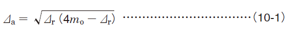
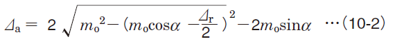
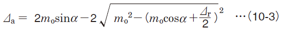
[Reference] Relationship between radial internal clearance and axial internal clearance
[Deep groove ball bearing]
[Double-row angular contact ball bearing]
[Matched pair angular contact ball bearing]
[Double/four-row and matched pair tapered roller bearing]