When bearings are mounted on shafts, locating method should be carefully determined. Shaft design examples for cylindrical bore bearings are given in "Table 14-4 Mounting designs for cylindrical bore bearings", and those for bearings with a tapered bore in "Table 14-5 Mounting designs for bearings with tapered bore".
Table 14-4 Mounting designs for cylindrical bore bearings
(a) Shaft locknut
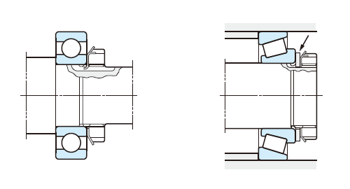
Lockwashers are used to prevent loosening of locknuts. When tapered roller bearings or angular contact ball bearings are transition-fitted to shafts, plain washers several mm thick as shown above (at right) should be added and tightened with nut.
(b) End plate
End of shaft should have bolt holes.
(c) Locating snap ring
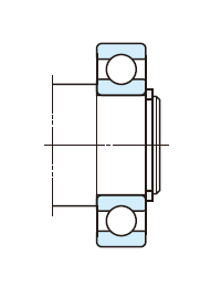
Used when the housing inside is limited, or to simplify shaft machining.
Table 14-5 Mounting designs for bearings with tapered bore
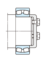
(d) Adapter assembly
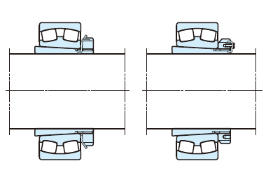
The simplest method for axial positioning is just to attach an adapter sleeve to the shaft and tighten the locknuts.
To prevent locknut loosening, lock-washer (not more than 180mm in shaft diameter) or lock plate (not less than 200mm in shaft diameter) are used.
(e) Withdrawal sleeve
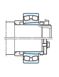
The locknut (above) or end plate (below) fixes the bearing with a withdrawal sleeve, which makes it easy to dismount the bearing.
(f) Shaft locknut
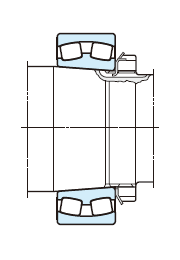
The shaft is threaded in the same way as shown in Fig. (a). The bearing is located by tightening locknut.
(g) Split ring
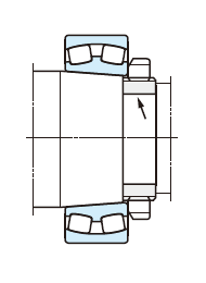
A split ring with threaded outside diameter is inserted into groove on the tapered shaft.
A key is often used to prevent the locknut and split ring from loosening.