15-3-1 Recommended preparation prior to mounting
1) Preparation of bearings
Wait until just before mounting before removing the bearings from their packaging to prevent contamination and rust.
Since the anti-corrosion oil covering bearings is a highly capable lubricant, the oil should not be cleaned off if the bearings are pre-lubricated, or when the bearings are used for normal operation. However, if the bearings are used in measuring instruments or at high rotation speed, the anti-corrosion oil should be removed using a clean detergent oil. After removal of the anti-corrosion oil, bearings should not be left for a long time because they rust easily.
2) Inspection of shafts and housings
Clean up the shaft and housing to check whether it has flaws or burrs as a result of machining.
Be very careful to completely remove lapping agents (SiC, Al2O3, etc.), casting sands, and chips from inside the housing.
Next, check that the dimensions, forms, and finish conditions of the shaft and the housing are accurate to those specified on the drawing.
The shaft diameter and housing bore diameter should be measured at the several points as shown in Figs. 15-1 and 15-2.
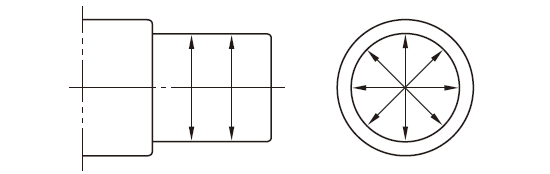
Fig. 15-1 Measuring points on shaft diameter
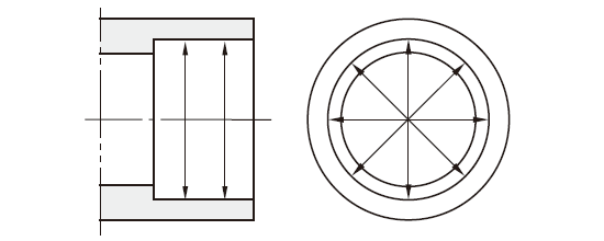
Fig. 15-2 Measuring points on housing bore diameter
Furthermore, fillet radius of shaft and housing, and the squareness of shoulders should be checked.
When using shaft and housing which have passed inspection, it is advisable to apply machine oil to each fitting surface just before mounting.
15-3-2 Bearing mounting
Mounting procedures depend on the type and fitting conditions of bearings.
For general bearings in which the shaft rotates, an interference fit is applied to inner rings, while a clearance fit is applied to outer rings.
For bearings in which the outer rings rotate, an interference fit is applied to the outer rings.
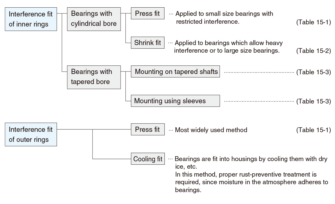
Interference fitting is roughly classified as shown here. The detailed mounting processes are described in Tables 15-1 to 15-3.
"Table 15-1 Press fit of bearings with cylindrical bores"
"Table 15-2 Shrink fit of cylindrical bore bearings"
"Table 15-3 Mounting bearings with tapered bores"
"Table 15-4 Mounting tapered bore spherical roller bearings"
ReferenceForce is necessary to press fit or remove bearings.
The force necessary to press fit or remove inner rings of bearings differs depending on the finish of shafts and how much interference the bearings allow.
The standard values can be obtained by using the following equations.
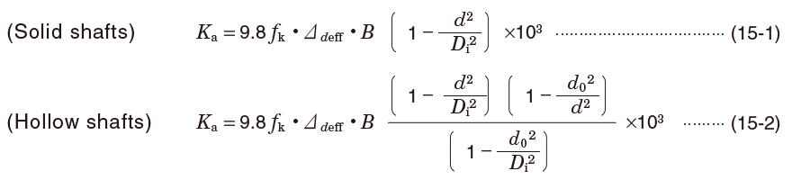
In equations (15-1) and (15-2),
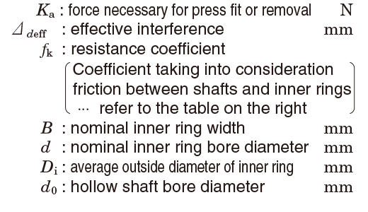
Value of resistance coefficient ƒk
| Conditions | ƒk |
|---|---|
|
4 |
|
6 |
|
5.5 |
|
4.5 |
|
10 |
|
11 |
Table 15-1 Press fit of bearings with cylindrical bores
| Mounting methods | Descriptions |
|---|---|

(a) Using press fit (the most widely used method) 
(b) Using bolts and nuts (screw hole should be provided at the shaft end) 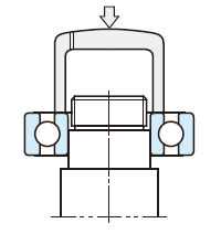
(c) Using hammers (only when there is no alternative measure) |
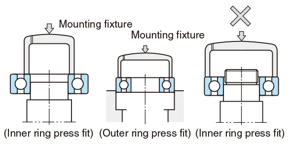
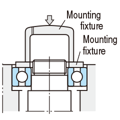
Simultaneous press fit of inner ring and outer ring |
Table 15-2 Shrink fit of cylindrical bore bearings
| Shrink fit | Descriptions |
|---|---|
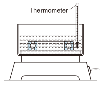
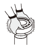
(a) Heating in an oil bath 
(b) Induction heater |
 [Notes]
|
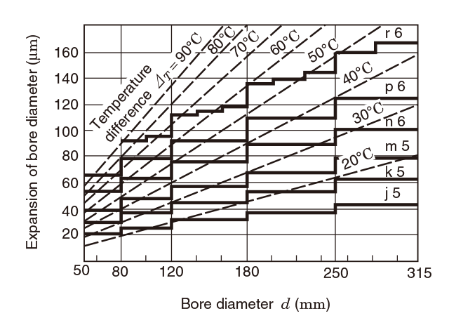
Fig. 15-3 Heating temperature and expansion of inner rings
[Remarks]
- Thick solid lines show the maximum interference value between bearings (class 0) and shafts (r6, p6, n6, m5, k5, j5) at normal temperature.
- Therefore, the heating temperature should be selected to gain a larger "expansion of the bore diameter" than the maximum interference values.
(When fitting class 0 bearings having a 90mm bore diameter to m5 shafts, this figure shows that heating temperature should be 40℃ higher than room temperature to produce expansion larger than the maximum interference value of 48μm. However, taking cooling during mounting into consideration, the temperature should be set 20 to 30℃ higher than the temperature initially required.)
Table 15-3 Mounting bearings with tapered bores
| Mounting methods | Descriptions |
|---|---|
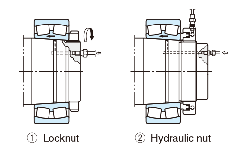
(a) Mounting on tapered shafts 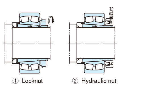
(b) Mounting by use of an adapter sleeve 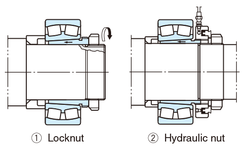
(c) Mounting by use of a withdrawal sleeve 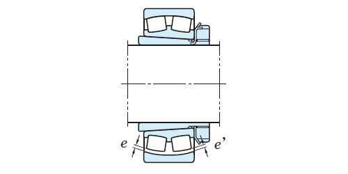
(d) Measuring clearances |
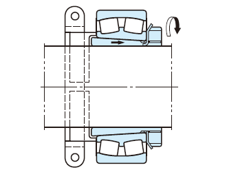
Locating bearing by use of a clamp

Clearance reduction can be measured by a thickness gage. First, stabilize the roller in the proper position and then insert the gage into the space between the rollers and the outer ring. Be careful that the clearance between both roller rows and the outer rings is roughly the same (e≒e'). Since the clearance may differ at different measuring points, take measurements at several positions.
|
Table 15-4 Mounting tapered bore spherical roller bearings
| Nominal bore diameter d mm |
Reduction of radial internal clearance µm |
Axial displacement, mm | Minimum required residual clearance, µm | |||||||
|---|---|---|---|---|---|---|---|---|---|---|
| 1/12 taper | 1/30 taper | C N clearance |
C 3 clearance |
C 4 clearance |
||||||
| over | up to | min. | max. | min. | max. | min. | max. | |||
| 24 | 30 | 15 | 20 | 0.27 | 0.35 | - | - | 10 | 20 | 35 |
| 30 | 40 | 20 | 25 | 0.32 | 0.4 | - | - | 15 | 25 | 40 |
| 40 | 50 | 25 | 35 | 0.4 | 0.5 | - | - | 20 | 30 | 45 |
| 50 | 65 | 30 | 40 | 0.45 | 0.6 | - | - | 25 | 35 | 55 |
| 65 | 80 | 35 | 50 | 0.55 | 0.75 | - | - | 35 | 40 | 70 |
| 80 | 100 | 40 | 55 | 0.65 | 0.85 | - | - | 40 | 50 | 85 |
| 100 | 120 | 55 | 70 | 0.85 | 1.05 | 2.15 | 2.65 | 45 | 65 | 100 |
| 120 | 140 | 65 | 90 | 1.0 | 1.2 | 2.5 | 3.0 | 55 | 80 | 110 |
| 140 | 160 | 75 | 100 | 1.1 | 1.35 | 2.75 | 3.4 | 55 | 90 | 130 |
| 160 | 180 | 80 | 110 | 1.2 | 1.5 | 3.0 | 3.8 | 60 | 100 | 150 |
| 180 | 200 | 90 | 120 | 1.4 | 1.7 | 3.5 | 4.3 | 70 | 110 | 170 |
| 200 | 225 | 100 | 130 | 1.55 | 1.85 | 3.85 | 4.6 | 80 | 120 | 190 |
| 225 | 250 | 110 | 140 | 1.7 | 2.05 | 4.25 | 5.1 | 90 | 130 | 210 |
| 250 | 280 | 120 | 160 | 1.8 | 2.3 | 4.5 | 5.75 | 100 | 140 | 230 |
| 280 | 315 | 130 | 180 | 2.0 | 2.5 | 5.0 | 6.25 | 110 | 150 | 250 |
| 315 | 355 | 150 | 200 | 2.3 | 2.8 | 5.75 | 7.0 | 120 | 170 | 270 |
| 355 | 400 | 170 | 220 | 2.5 | 3.1 | 6.25 | 7.75 | 130 | 190 | 300 |
| 400 | 450 | 190 | 240 | 2.8 | 3.4 | 7.0 | 8.5 | 140 | 210 | 330 |
| 450 | 500 | 210 | 270 | 3.1 | 3.8 | 7.75 | 9.5 | 160 | 230 | 360 |
| 500 | 560 | 240 | 310 | 3.5 | 4.3 | 8.75 | 10.8 | 170 | 260 | 370 |
| 560 | 630 | 260 | 350 | 3.9 | 4.8 | 9.75 | 12.0 | 200 | 300 | 410 |
| 630 | 710 | 300 | 390 | 4.3 | 5.3 | 10.8 | 13.3 | 210 | 320 | 460 |
| 710 | 800 | 340 | 430 | 4.8 | 6.0 | 12.0 | 15.0 | 230 | 370 | 530 |
| 800 | 900 | 370 | 500 | 5.3 | 6.7 | 13.3 | 16.8 | 270 | 410 | 570 |
| 900 | 1000 | 410 | 550 | 5.9 | 7.4 | 14.8 | 18.5 | 300 | 450 | 640 |
[Remark]
The values for reduction of radial internal clearance listed above are values obtained when mounting bearings with CN clearance on solid shafts. In mounting bearings with C3 clearance, the maximum value listed above should be taken as the standard.