Sealing devices not only prevent foreign matter (dirt, water, metal powder) from entering, but prevent lubricant inside from leaking. If the sealing device fails to function satisfactorily, foreign matter or leakage will cause bearing damage as a result of malfunction or seizure.
Therefore, it is necessary to design or choose the most suitable sealing devices as well as to choose the proper lubricating measures according to operating conditions.
Sealing devices may be divided into non-contact and contact types according to their structure.
They should satisfy the following conditions :
- Free from excessive friction (heat generation)
- Easy maintenance (especially ease of mounting and dismounting)
- As low cost as possible
14-4-1 Non-contact type sealing devices
A non-contact type sealing device, which includes oil groove, flinger (slinger), and labyrinth, eliminates friction because it does not have a contact point with the shaft.
These devices utilize narrow clearance and centrifugal force and are especially suitable for operation at high rotation speed and high temperature.
Table 14-6 Non-contact type sealing devices
(1) Oil groove
(a)
(b)
(c)
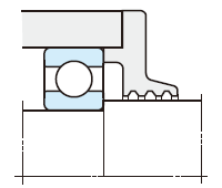
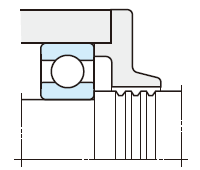
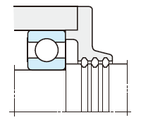
- This kind of seal having more than three grooves at the narrow clearance between the shaft and housing cover, is usually accompanied by other sealing devices except when it is used with grease lubrication at low rotation speed.
- Preventing entrance of contaminants can be improved by filling the groove with calcium grease (cup grease) having a consistency of 150 to 200.
- The clearance between the shaft and housing cover should be as narrow as possible. Recommended clearances are as follows.
Shaft diameter of less than 50mm (0.25 − 0.4mm)
Shaft diameter of over 50mm (0.5 − 1mm) - Recommended dimensions for the oil groove are as follows.
Width (2 - 5mm)
Depth (4 - 5mm)
(2) Flinger (slinger)
(d) Flinger attached inside
(e) Flinger attached outside
(f) Cover type flinger
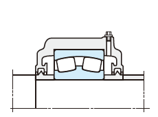
(g) Oil thrower
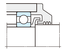
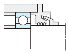
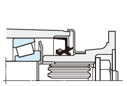
- A flinger utilizes centrifugal force to splash away the oil and dirt. It produces an air stream which prevents oil leakage and dirt by a pumping action. In many cases, this device is used together with other sealing devices.
- A flinger installed inside the housing (Fig. d) provides an inward pumping action, preventing lubricant leakage; and, when installed outside (Fig. e), the outward pumping action prevents lubricant contamination.
- A cover type flinger (Fig. f) splashes away dirt and dust by centrifugal force.
- The oil thrower, shown in (Fig. g), is a kind of flinger. An annular ridge on the shaft or a ring fitted onto the shaft utilizes centrifugal force to prevent the lubricant from flowing out.
(3) Labyrinth
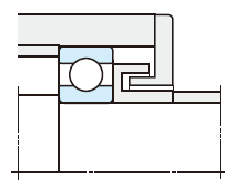
(h) Axial labyrinth
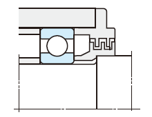
(i) Radial labyrinth
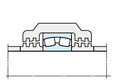
(j) Aligning labyrinth
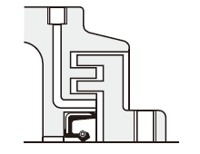
(k) Axial labyrinth with greasing feature
- A labyrinth provides clearance in the shape of engagements between the shaft and housing.
It is the most suitable for prevention of lubricant leakage at high rotation speed. - Though an axial labyrinth, shown in (Fig. h), is popular because of its ease of mounting, the sealing effect is better in a radial labyrinth, shown in (Fig. i).
- An aligning labyrinth (Fig. j) is used with selfaligning type bearings.
- In the cases of (Fig. i) and (Fig. j), the housing or the housing cover should be split.
- Recommended labyrinth clearances are given in the following table.
Shaft diameter Radial clearance Axial clearance 50mm or less 0.25 - 0.4mm 1 - 2mm Over 50mm 0.5 - 1mm 3 - 5mm - To improve sealing effect, fill the labyrinth clearance with grease, shown in (Fig. k).
14-4-2 Contact type sealing devices
This type provides a sealing effect by means of the contact of its end with the shaft and are manufactured from synthetic rubber, synthetic resin, or felt.
The synthetic rubber oil seal is most popular.
1) Oil seals
Many types and sizes of oil seals, as a finished part, have been standardized. JTEKT produces various oil seals. The names and functions of each oil seal part are shown in "Fig. 14-8 Names of oil seal parts" and "Table 14-7 Complete list of oil seal part functions". "Table 14-8 Typical oil seal types" provides a representative example.
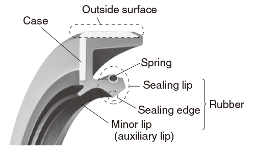
Fig. 14-8 Names of oil seal parts
Table 14-7 Complete list of oil seal part functions
| Names | Functions |
|---|---|
| Sealing edge | Prevents fluid leakage by making contact with rotating shaft. (The contact surface of the sealing edge with the shaft should always filled with lubricant, so as to maintain an oil film therein.) |
| Sealing lip and spring | Provides proper pressure on the sealing edge to maintain stable contact. Spring provides proper pressure on the lip and maintains such pressure for a long time. |
| Outside surface | Fixes the oil seal to the housing and prevents fluid leakage through the fitting surface. (Comes encased in metal cased type or rubber covered type.) |
| Case | Strengthens seal. |
| Minor lip (auxiliary lip) |
Prevents entry of contaminants. (In many cases, the space between the sealing lip and minor lip is filled with grease.) |
Table 14-8 Typical oil seal types
| With case | With inner case | Without case | |
|---|---|---|---|
| Without spring | With spring | With spring | |
 |
 |
 |
 |
 |
 |
 |
- |
|
|
||
Oil seals without minor lips are mounted in different directions according to their operating conditions (shown in Fig. 14-9).
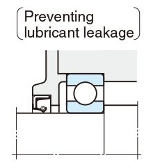
(a) Front facing inside
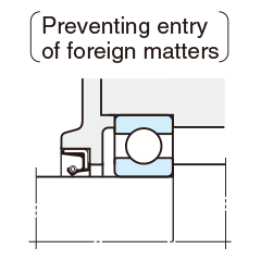
(b) Front facing outside
Fig. 14-9 Direction of sealing lips and their purpose
When the seal is used in a dirty operating environment, or penetration of water is expected, it is advisable to have two oil seals combined or to have the space between the two sealing lips be filled with grease.
(shown in Fig. 14-10)
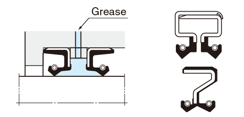
Fig. 14-10 Seals used in a dirty operating environment
Respective seal materials possess different properties. Accordingly, as shown in Table 14-9, allowable lip speed and operating temperature differ depending on the materials. Therefore, by selecting proper materials, oil seals can be used for sealing not only lubricants but also chemicals including alcohol, acids, alkali, etc.
Table 14-9 Allowable lip speed and operating temperature range of oil seals
| Seal material | Allowable lip speed (m/s) | Operating temperature range (℃) |
|---|---|---|
| NBR | 15 | - 40 to + 120 |
| Acrylic rubber | 25 | - 30 to + 150 |
| Silicone rubber | 32 | - 50 to + 170 |
| Fluoro rubber | 32 | - 20 to + 180 |
To ensure the maximum sealing effect of the oil seal, the shaft materials, surface roughness and hardness should be carefully chosen.
Table 14-10 shows the recommended shaft conditions.
Table 14-10 Recommended shaft conditions
| Material | Machine structure steel, low alloy steel and stainless steel |
|---|---|
| Surface hardness | For low speed : harder than 30 HRC For high speed : harder than 50 HRC |
| Surface roughness (Ra) | 0.2 - 0.6a (A surface which is excessively rough may cause oil leakage or abrasion ; whereas an excessively fine surface may cause sealing lip seizure, preventing the oil film from forming. Surface must also be free of spiral grinding marks.) |
2) Felt seals and others
Although felt seals have been used conventionally, it is recommended to replace them with rubber oil seals because the use of felt seals are limited to the following conditions.
- Light dust protection
- Allowable lip speed : not higher than 5m/s
Contact type sealing devices include mechanical seals, O-rings and packings other than those described herein.
(JTEKT manufactures various oil seals ranging from those illustrated in "Table 14-8 Typical oil seal types" to special seals for automobiles, large seals for rolling mills, mud resistance seals, pressure resistance seals, outer seals for rotating housings and O-rings.
For details, refer to JTEKT separate catalog "Oil seals & O-rings"
(CAT. NO. R2001E).)

