5-2-1 Basic dynamic load rating C
The basic dynamic load rating is either pure radial (for radial bearings) or central axial load (for thrust bearings) of constant magnitude in a constant direction, under which the basic rating life of 1 million revolutions can be obtained, when the inner ring rotates while the outer ring is stationary, or vice versa. The basic dynamic load rating, which represents the capacity of a bearing under rolling fatigue, is specified as the basic dynamic radial load rating (Cr) for radial bearings, and basic dynamic axial load rating (Ca) for thrust bearings. These load ratings are listed in the specification table.
These values are prescribed by ISO 281/ 1990, and are subject to change by conformance to the latest ISO standards.
5-2-2 Basic rating life L10
The basic rating life L10 is a service life of 90 % reliability when used under normal usage conditions for bearings of high manufacturing quality where the inside of the bearing is of a standard design made from bearing steel materials specified in JIS or equivalent materials.
The relationship between the basic dynamic load rating, dynamic equivalent load, and basic rating life of a bearing can be expressed using equation (5-1). This life calculation equation does not apply to bearings that are affected by factors such as plastic deformation of the contact surfaces of raceways and rolling elements due to extremely high load conditions (when P exceeds either the basic static load rating C0 (refer to Basic static load rating and static equivalent load) or 0.5C) or, conversely, to bearings that are affected by factors such as the contact surfaces of raceways and rolling elements slipping due to extremely low load conditions.
If conditions like these may be encountered, consult with JTEKT.
It is convenient to express the basic rating life in terms of time, using equation (5-2), when a bearing is used for operation at a constant speed; and, in terms of traveling distance (km), using equation (5-3), when a bearing is used in railway rolling stock or automobiles.
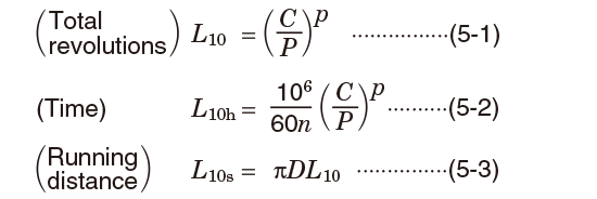
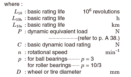
Accordingly, where the dynamic equivalent load is P, and rotational speed is n, equation (5-4) can be used to calculate the basic dynamic load rating C; the bearing size most suitable for a specified purpose can then be selected, referring to the bearing specification table.
The recommended bearing service life differs depending on the machines with which the bearing is used, as shown in Table 5-5 Recommended bearing service life (reference).

Reference
The equations using a service life coefficient (ƒh) and rotational speed coefficient (ƒn) respectively, based on equation (5-2), are as follows :
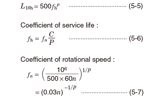
For reference, the values of ƒn, ƒh, and L10h can be easily obtained by employing the nomograph attached to this catalog, as an abbreviated method.
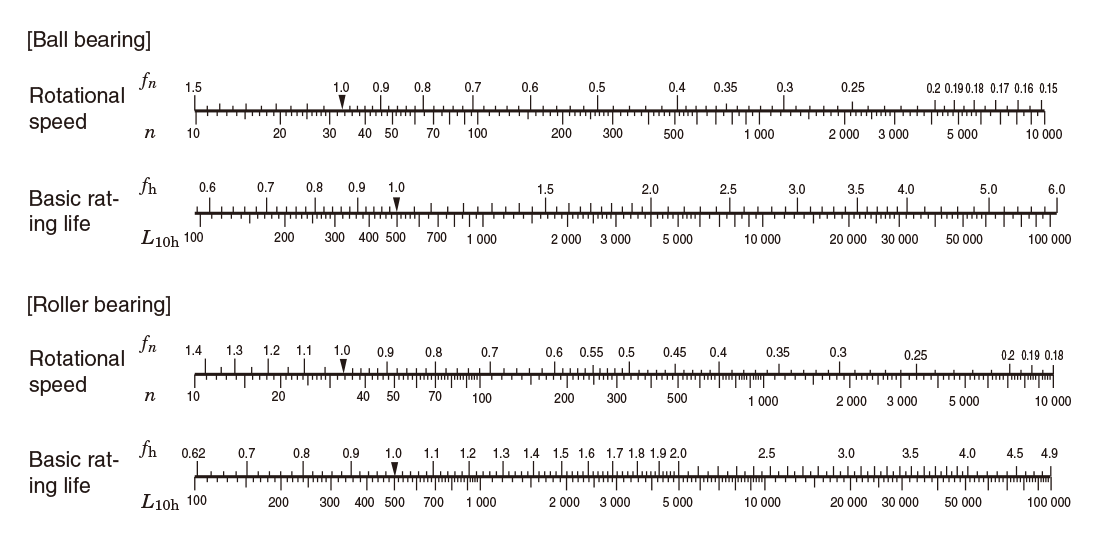
[Reference] Rotational speed (n) and its coefficients (ƒn), and service life coefficient (ƒh) and basic rating life (L10h)
5-2-3 Correction of basic dynamic load rating for high temperature use and dimension stabilizing treatment
In high temperature operation, bearing material hardness deteriorates, as material compositions are altered. As a result, the basic dynamic load rating is diminished. Once altered, material composition is not recovered, even if operating temperatures return to normal.
Therefore, for bearings used in high temperature operation, the basic dynamic load rating should be corrected by multiplying the basic dynamic load rating values specified in the bearing specification table by the temperature coefficient values in Table 5-1.
Table 5-1 Temperature coefficient values
| Bearing temperature, ℃ | 125 | 150 | 175 | 200 | 250 |
|---|---|---|---|---|---|
| Temperature coefficient | 1 | 1 | 0.95 | 0.90 | 0.75 |
Since normal heat treatment is not effective in maintaining the original bearing size in extended operation at 120℃ or higher, dimension stabilizing treatment is necessary. Dimension stabilizing treatment codes and their effective temperature ranges are described in Table 5-2.
Since dimension stabilizing treatment diminishes material hardness, the basic dynamic load rating may be reduced for some types of bearings.
Table 5-2 Dimension stabilizing treatment
| Dimension stabilizing treatment code | Effective temperature range |
|---|---|
| S0 | Over 100℃, up to 150℃ |
| S1 | Over 150℃, up to 200℃ |
| S2 | Over 200℃, up to 250℃ |
5-2-4 Modified rating life Lnm
The life of rolling bearings was standardized as a basic rating life in the 1960s, but in actual applications, sometimes the actual life and the basic rating life have been quite different due to the lubrication status and the influence of the usage environment. To make the calculated life closer to the actual life, a corrected rating life has been considered since the 1980s. In this corrected rating life, bearing characteristic factor α2 (a correction factor for the case in which the characteristics related to the life are changed due to the bearing materials, manufacturing process, and design) and usage condition factor a3 (a correction factor that takes into account usage conditions that have a direct influence on the bearing life, such as the lubrication) or factor α23 formed from the interdependence of these two factors, are considered with the basic rating life. These factors were handled differently by each bearing manufacturer, but they have been standardized as a modified rating life in ISO 281 in 2007. In 2013, JIS B 1518 (dynamic load ratings and rating life) was amended to conform to the ISO.
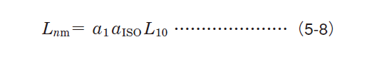
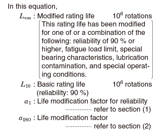
The basic rating life (L10) shown in equation (5-1) is the (fatigue) life with a dependability of 90 % under normal usage conditions for rolling bearings that have standard factors such as internal design, materials, and manufacturing quality. JIS B 1518:2013 specifies a calculation method based on ISO 281:2007. To calculate accurate bearing life under a variety of operating conditions, it is necessary to consider elements such as the effect of changes in factors that can be anticipated when using different reliabilities and system approaches, and interactions between factors. Therefore, the specified calculation method considers additional stress due to the lubrication status, lubricant contamination, and fatigue load limit Cu (refer to b) Fatigue load limit Cu) on the inside of the bearing. The life that uses this life modification factor αISO, which considers the above factors, is called modified rating life Lnm and is calculated with the following equation (5-8).
[Remark]
When bearing dimensions are to be selected given Lnm greater than 90 % in reliability, the strength of shaft and housing must be considered.
(1) Life modification factor for reliability α1
The term "reliability" is defined as "for a group of apparently identical rolling bearings, operating under the same conditions, the percentage of the group that is expected to attain or exceed a specified life" in ISO 281:2007. Values of α1 used to calculate a modified rating life with a reliability of 90 % or higher (a failure probability of 10 % or less) are shown in Table 5-3.
Table 5-3 Life modification factor for reliability α1
| Reliability, % | Lnm | α1 |
|---|---|---|
| 90 | L10m | 1 |
| 95 | L5m | 0.64 |
| 96 | L4m | 0.55 |
| 97 | L3m | 0.47 |
| 98 | L2m | 0.37 |
| 99 | L1m | 0.25 |
| 99.2 | L0.8m | 0.22 |
| 99.4 | L0.6m | 0.19 |
| 99.6 | L0.4m | 0.16 |
| 99.8 | L0.2m | 0.12 |
| 99.9 | L0.1m | 0.093 |
| 99.92 | L0.08m | 0.087 |
| 99.94 | L0.06m | 0.080 |
| 99.95 | L0.05m | 0.077 |
(Citation from JIS B 1518:2013)
(2) Life modification factor αISO
a) System approach
The various influences on bearing life are dependent on each other. The system approach of calculating the modified life has been evaluated as a practical method for determining life modification factor αISO (ref. Fig. 5-1). Life modification factor αISO is calculated with the following equation. A diagram is available for each bearing type (radial ball bearings, radial roller bearings, thrust ball bearings, and thrust roller bearings). (Each diagram (Figs. 5-2 to 5-5) is a citation from JIS B 1518:2013.)
Note that in practical use, this is set so that life modification factor αISO≦50.
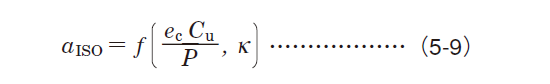
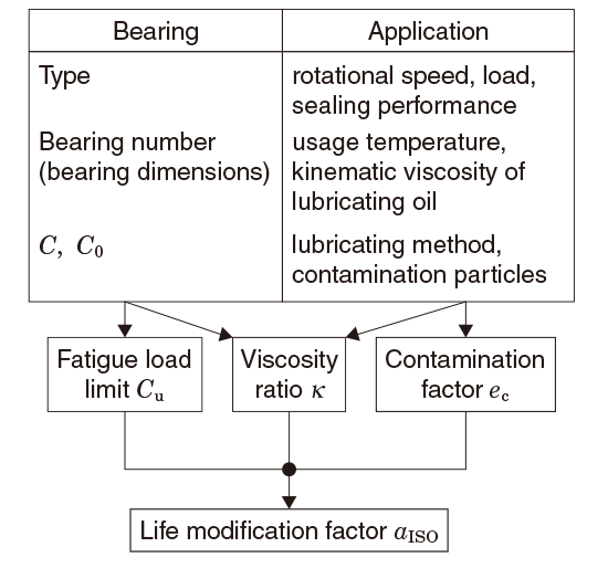
Fig. 5-1 System approach
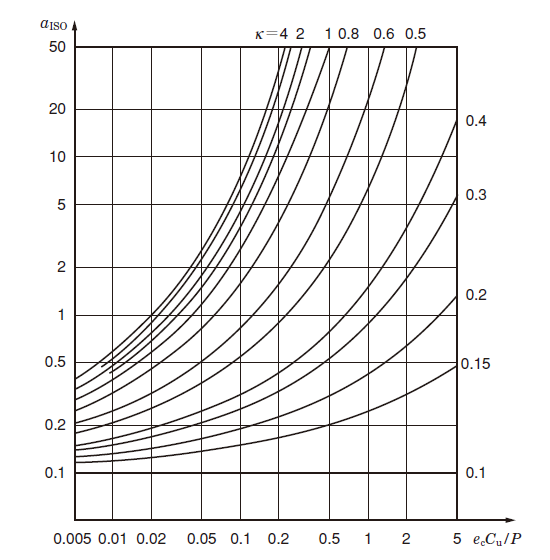
Fig. 5-2 Life modification factor αISO (Radial ball bearings)
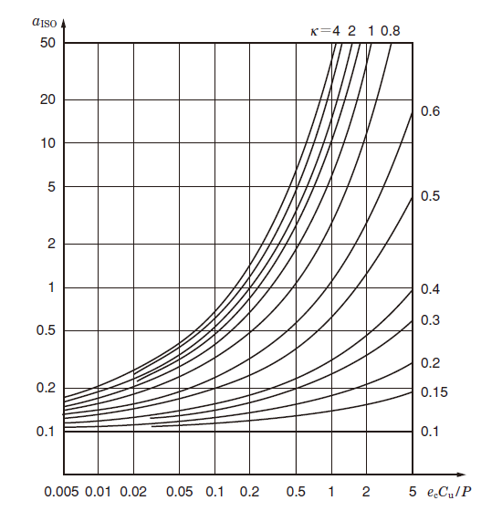
Fig. 5-3 Life modification factor αISO (Radial roller bearings)
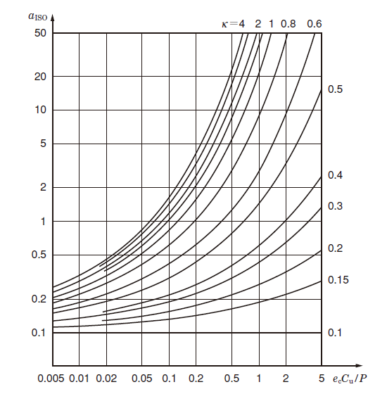
Fig. 5-4 Life modification factor αISO (Thrust ball bearings)
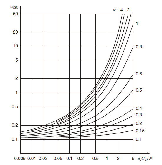
Fig. 5-5 Life modification factor αISO (Thrust roller bearings)
(Figs. 5-2 to 5-5 Citation from JIS B 1518:2013)
b) Fatigue load limit Cu
hat has equivalent quality, the fatigue life is unlimited so long as the load condition does not exceed a certain value and so long as the lubrication conditions, lubrication cleanliness class, and other operating conditions are favorable. For general high-quality materials and bearings with high manufacturing quality, the fatigue stress limit is reached at a contact stress of approximately 1.5 GPa between the raceway and rolling elements. If one or both of the material quality and manufacturing quality are low, the fatigue stress limit will also be low.
The term "fatigue load limit" Cu is defined as "bearing load under which the fatigue stress limit is just reached in the most heavily loaded raceway contact" in ISO 281:2007. and is affected by factors such as the bearing type, size, and material.
For details on the fatigue load limits of special bearings and other bearings not listed in this catalog, contact JTEKT.
c) Contamination factor ec
If solid particles in the contaminated lubricant are caught between the raceway and the rolling elements, indentations may form on one or both of the raceway and the rolling elements. These indentations will lead to localized increases in stress, which will decrease the life. This decrease in life attributable to the contamination of the lubricant can be calculated from the contamination level as contamination factor ec.
Dpw shown in this table is the pitch diameter of ball/roller set, which is expressed simply as Dpw=(D+d)/2. (D: Outside diameter, d: Bore diameter)
For information such as details on special lubricating conditions or detailed investigations, contact JTEKT.
Table 5-4 Values of contamination factor ec
| Contamination level | ec | |
|---|---|---|
| Dpw<100mm | Dpw≧100mm | |
| Extremely high cleanliness: The size of the particles is approximately equal to the thickness of the lubricant oil film, this is found in laboratory-level environments. | 1 | 1 |
| High cleanliness: The oil has been filtered by an extremely fine filter, this is found with standard grease-packed bearings and sealed bearings. | 0.8~0.6 | 0.9~0.8 |
| Standard cleanliness: The oil has been filtered by a fine filter, this is found with standard grease-packed bearings and shielded bearings. | 0.6~0.5 | 0.8~0.6 |
| Minimal contamination: The lubricant is slightly contaminated. | 0.5~0.3 | 0.6~0.4 |
| Normal contamination: This is found when no seal is used and a coarse filter is used in an environment in which wear debris and particles from the surrounding area penetrate into the lubricant. | 0.3~0.1 | 0.4~0.2 |
| High contamination: This is found when the surrounding environment is considerably contaminated and the bearing sealing is insufficient. | 0.1~0 | 0.1~0 |
| Extremely high contamination | 0 | 0 |
(Table 5-4 Citation from JIS B 1518:2013)
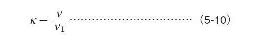
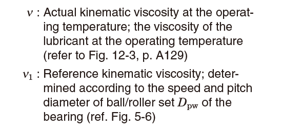
d) Viscosity ratio κ
The lubricant forms an oil film on the roller contact surface, which separates the raceway and the rolling elements. The status of the lubricant oil film is expressed by viscosity ratio κ, the actual kinematic viscosity at the operating temperature ν divided by the reference kinematic viscosity ν1 as shown in the following equation.
A κ greater than 4, equal to 4, or less than 0.1 is not applicable.
For details on lubricants such as grease and lubricants with extreme pressure additives, contact JTEKT.
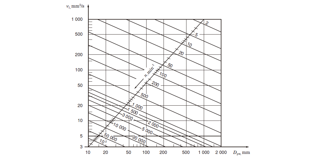
(Fig. 5-6 Citation from JIS B 1518:2013)
Fig. 5-6 Reference kinematic viscosity ν1
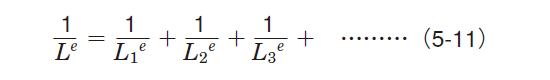
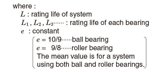
5-2-5 Service life of bearing system comprising two or more bearings
Even for systems which comprise two or more bearings, if one bearing is damaged, the entire system malfunctions.
Where all bearings used in an application are regarded as one system, the service life of the bearing system can be calculated using the following equation,
[Example]
When a shaft is supported by two roller bearings whose service lives are 50 000 hours and 30 000 hours respectively, the rating life of the bearing system supporting this shaft is calculated as follows, using equation (5-11) :
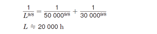
The equation suggests that the rating life of these bearings as a system becomes shorter than that of the bearing with the shorter life.
This fact is very important in estimating bearing service life for applications using two or more bearings.
5-2-6 Applications and recommended bearing service life
Since longer service life does not always contribute to economical operation, the most suitable service life for each application and operating conditions should be determined.
For reference, Table 5-5 describes recommended service life in accordance with the application, as empirically determined.
Table 5-5 Recommended bearing service life (reference)
| Operating condition | Application | Recommended service life (h) |
|---|---|---|
| Short or intermittent operation | Household electric appliance, electric tools, agricultural equipment, heavy cargo hoisting equipment | 4000~8000 |
| Not extended duration, but stable operation required | Household air conditioner motors, construction equipment, conveyers, elevators | 8000~12000 |
| Intermittent but extended operation | Rolling mill roll necks, small motors, cranes | 8000~12000 |
| Motors used in factories, general gears | 12000~20000 | |
| Machine tools, shaker screens, crushers | 20000~30000 | |
| Compressors, pumps, gears for essential use | 40000~60000 | |
| Daily operation more than 8 hr. or continuous extended operation | Escalators | 12000~20000 |
| Centrifugal separators, air conditioners, air blowers, woodworking equipment, passenger coach axle journals | 20000~30000 | |
| Large motors, mine hoists, locomotive axle journals, railway rolling stock traction motors | 40000~60000 | |
| Paper manufacturing equipment | 100000~200000 | |
| 24 hr. operation (no failure allowed) | Water supply facilities, power stations, mine water discharge facilities | 100000~200000 |