In selecting bearings, the most important thing is to fully understand the operating conditions of the bearings.
The main factors to be considered are listed in Table 3-1, while bearing types are listed in Table 3-2.
Table 3-1 Selection of bearing type
| Items to be considered | Selection method | Reference page No. | |
|---|---|---|---|
| 1) Installation space | Bearing can be installed in target equipment |
|
Reference:Boundary dimensions |
| 2)Load | Load magnitude, type and direction which applied (Load resistance of bearing is specified in terms of the basic load rating, and its value is specified in the bearing specification table.) |
|
Reference:Table 3-2 Performance comparison of bearing type Reference:Fit selection |
| 3)Rotational speed | Response to rotational speed of equipment in which bearings will be installed (The limiting speed for bearing is expressed as allowable speed, and this value is specified in the bearing specification table.) |
|
Reference:Table 3-2 Performance comparison of bearing type Reference:Limiting speed |
| 4)Running accuracy | Accurate rotation delivering required performance (Dimension accuracy and running accuracy of bearings are provided by JIS, etc.) |
|
Reference:Table 3-2 Performance comparison of bearing type Reference:Tolerances and tolerance classes for bearings |
| 5)Rigidity | Rigidity that delivers the bearing performance required (When load is applied to a bearing, elastic deformation occurs at the point where its rolling elements contact the raceway surface. The higher the rigidity that bearings possess, the better they control elastic deformation.) |
|
Reference:Table 3-2 Performance comparison of bearing type Reference:Preload |
| 6)Misalignment (aligning capability) |
Operating conditions which cause misalignment (shaft deflection caused by load, inaccuracy of shaft and housing, mounting errors) can affect bearing performance (Allowable misalignment (in angle) for each bearing type is described in the section before the bearing specification table, to facilitate determination of the self-aligning capability of bearings.) |
|
Reference:Table 3-2 Performance comparison of bearing type |
| 7)Mounting and dismounting | Methods and frequency of mounting and dismounting required for periodic inspection |
|
Reference:Table 3-2 Performance comparison of bearing type |
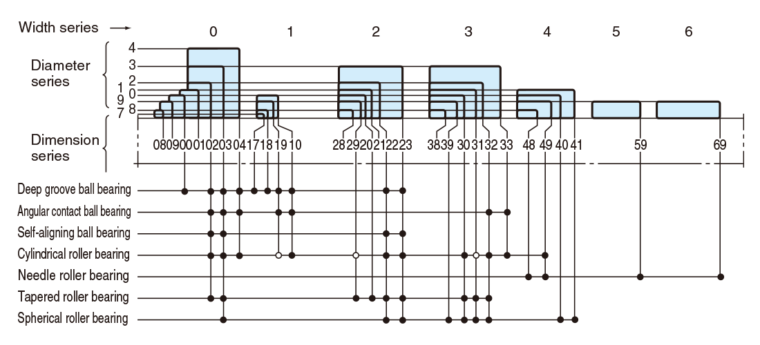
Fig. 3-1 Radial bearing dimension series
Table 3-2 Performance comparison of bearing type
| Deep groove ball bearing | Angular contact ball bearing | Four-point contact ball bearing | Selfaligning ball bearing | Cylindrical roller bearing | Reference page No. | |||||||
|---|---|---|---|---|---|---|---|---|---|---|---|---|
| Singlerow | Matched pair or stack | Doublerow | NU・N | NJ・NF | NUP・NH | NN・NNU | ||||||
 |
 |
 |
 |
 |
 |
 |
 |
 |
 |
- | ||
| Load resistance | Radial load |  |
|
 |
|
|
|
|
|
|
|
- |
| Axial load |  |
 |
※ |
※ |
|
 |
 |
|
|
|
- | |
| Combined load radial and axial | |
|
|
|
|
|
|
|
|
|
- | |
| Vibration or impact load | |
|
|
|
|
|
|
|
|
|
- | |
| High speed adaptability | |
|
|
|
|
|
|
|
|
|
Reference:Table 3-1 Selection of bearing type Reference:Limiting speed |
|
| High accuracy | |
|
|
|
|
|
Reference:Table 3-1 Selection of bearing type Reference:Tolerances and tolerance classes for bearings Reference:Purpose and method of lubrication |
|||||
| Low noise level/low torque | |
|
Reference:Table 3-1 Selection of bearing type | |||||||||
| Rigidity | |
|
|
|
|
|
Reference:Table 3-1 Selection of bearing type | |||||
| Misalignment | |
|
|
|
|
|
|
|
|
|
Reference:Table 3-1 Selection of bearing type Description before specification table |
|
| Inner and outer ring separability | |
|
|
|
 ※ ※ |
|
|
|
|
|
- | |
| Arrangement | Fixed side | |
|
|
※ |
|
|
|
|
|
|
Reference:Selection of bearing arrangement |
| Free side |  |
|
|
|
|
|
|
|
|
Reference:Selection of bearing arrangement | ||
| Remarks | A pair of bearings mounted facing each other. | *DT arrangement is effective for one direction only. | *Filling slot type is effective for one direction only. | *Nonseparable type is also available. | - | |||||||
| Needle roller bearing (machined ring type) | Tapered roller bearing | Spherical roller bearing | Thrust ball bearing | Double direction angular contact thrust ball bearing | Cylindrical roller thrust bearing | Needle roller thrust bearing | Tapered roller thrust bearing | Spherical thrust roller bearing | Reference page No. | ||||
|---|---|---|---|---|---|---|---|---|---|---|---|---|---|
| Singlerow | Double-row, four-row | With flat back faces | With aligning seat race | ||||||||||
 |
 |
 |
 |
 |
 |
 |
 |
 |
 |
 |
- | ||
| Load resistance | Radial load | |
|
|
|
|
|
|
|
|
|
|
- |
| Axial load | |
|
|
|
※ |
※ |
|
|
|
|
|
- | |
| Combined load radial and axial | |
|
|
|
|
|
|
|
|
|
|
- | |
| Vibration or impact load | |
|
|
|
|
|
|
|
|
|
|
- | |
| High speed adaptability | |
|
|
|
|
|
|
|
|
|
|
Reference:Table 3-1 Selection of bearing type Reference:Limiting speed |
|
| High accuracy | |
|
|
Reference:Table 3-1 Selection of bearing type Reference:Tolerances and tolerance classes for bearings Reference:Purpose and method of lubrication |
|||||||||
| Low noise level/low torque | Reference:Table 3-1 Selection of bearing type | ||||||||||||
| Rigidity | |
|
|
|
|
|
|
Reference:Table 3-1 Selection of bearing type | |||||
| Misalignment | |
|
|
|
|
|
|
|
|
|
|
Reference:Table 3-1 Selection of bearing type Description before specification table |
|
| Inner and outer ring separability | |
|
|
|
|
|
|
|
※ |
|
|
- | |
| Arrangement | Fixed side | |
|
|
|
Reference:Selection of bearing arrangement | |||||||
| Free side | |
|
|
Reference:Selection of bearing arrangement | |||||||||
| Remarks | A pair of bearings mounted facing each other. | *Double direction bearings are effective for both directions. | *Non-separable type is also available. | - | |||||||||
|
Excellent |
|
Good |
|
Fair |
|
Unacceptable |
|
Both directions |
|
One direction only |
|
Acceptable |
|
Acceptable, but shaft shrinkage must be compensated for. |