Bearing tolerances and permissible values for the boundary dimensions and running accuracy of bearings are specified.
These tolerances are prescribed in JIS B 1514-1, JIS B 1514-2, and JIS B 1514-3 (roller bearings - bearing tolerances part 1: radial bearings, part 2: thrust bearings, and part 3: permissible values for chamfer dimensions). (These JIS standards are based on ISO standards.)
Bearing tolerances are standardized by classifying bearings into the following six classes (accuracy in tolerances becomes higher in the order described): 0, 6X, 6, 5, 4 and 2.
Class 0 bearings offer adequate performance for general applications; and, bearings of class 5 or higher are required for demanding applications and operating conditions including those described in Table 7-1 High precision bearing applications.
These tolerances follow ISO standards, but some countries use different names for them. Tolerances for each bearing class, and organizations concerning bearings are listed in Table 7-2 Bearing type and tolerance class.
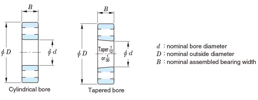
- Boundary dimension accuracy (items on shaft and housing mounting dimensions)
- Tolerances for bore diameter, outside diameter, ring width, assembled bearing width
- Tolerances for set bore diameter and set outside diameter of rollers
- Tolerance limits for chamfer dimensions
- Permissible values for width variation
- Tolerance and permissible values for tapered bore
- Running accuracy (items on runout of rotating elements)
- Permissible values for radial and axial runout of inner and outer rings
- Permissible values for perpendicularity of inner ring face
- Permissible values for perpendicularity of outer ring outside surface
- Permissible values for thrust bearing raceway thickness
Accuracies for dimensions and running of each bearing type are listed in
Tables 7-3 Radial bearing tolerances (tapered roller bearings excluded) = JIS B 1514-1 =,
Tables 7-4 Tolerances for measuring instrument ball bearings (inch series) = ANSI/ABMA standards = (reference),
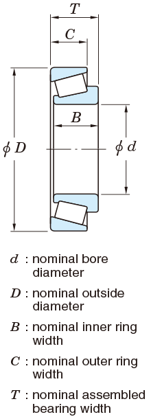
Tables 7-5 Tolerances for metric series tapered roller bearings = JIS B 1514-1 =,
Tables 7-6 Tolerances for metric series double-row and four-row tapered roller bearings (class 0) = BAS 1002 =,
Tables 7-7 Tolerances and permissible values for inch series tapered roller bearings = ANSI/ABMA 19 =,
Table 7-8 Tolerances for metric J series tapered roller bearings1),
Tables 7-9 Tolerances for thrust ball bearings = JIS B 1514-2 =,
Tables 7-10 Tolerances for spherical thrust roller bearings (class 0) = JIS B 1514-2 =;
and, tolerances for tapered bore and limit values for chamfer dimensions of radial bearings are in
Tables 7-11 Tolerances and permissible values for tapered bores of radial bearings (class 0 ⋅⋅⋅ JIS B 1514-1) and
7-12 Tolerances and permissible values for flanged radial ball bearings.
Table 7-1 High precision bearing applications
| Required performance | Applications | Tolerance class |
|---|---|---|
| High accuracy in runout is required for rolling elements. | Acoustic / visual equipment spindles (VTR, tape recorders) | P5, P4 |
| Radar / parabola antenna slewing shafts | P4 | |
| Machine tool spindles | P5, P4, P2, ABEC9 | |
| Computers, magnetic disc spindles | P5, P4, P2, ABEC9 | |
| Aluminum foil roll necks | P5 | |
| Multi-stage mill backing bearings | P4 | |
| High speed rotation | Dental spindles | P2, ABMA5P, ABMA7P |
| Superchargers | P5, P4 | |
| Jet engine spindles and accessories | P5, P4 | |
| Centrifugal separators | P5, P4 | |
| LNG pumps | P5 | |
| Turbo molecular pump spindles and touch-down | P5, P4 | |
| Machine tool spindles | P5, P4, P2, ABEC9 | |
| Tension reels | P5, P4 | |
| Low friction or low friction variation is required. | Control equipment (synchronous motors, servomotors, gyro gimbals) | P4, ABMA7P |
| Measuring instruments | P5 | |
| Machine tool spindles | P5, P4, P2, ABEC9 |
Table 7-2 Bearing type and tolerance class
| Bearing type | Applied standards | Applied tolerance class | Tolerance table | |||||||
|---|---|---|---|---|---|---|---|---|---|---|
| Deep groove ball bearing | JIS B 1514-1 | Class 0 | - | Class 6 | Class 5 | Class 4 | Class 2 | Table 7-3 | ||
| Angular contact ball bearing | Class 0 | - | Class 6 | Class 5 | Class 4 | Class 2 | ||||
| Self-aligning ball bearing | Class 0 | - | - | - | - | - | ||||
| Cylindrical roller bearing | Class 0 | - | Class 6 | Class 5 | Class 4 | Class 2 | ||||
| Needle roller bearing (machined ring type) | JIS B 1536-1 | Class 0 | - | - | - | - | - | |||
| Tapered roller bearing | Metric series (single-row) | JIS B 1514-1 | Class 0 | Class 6X | (Class 6) | Class 5 | Class 4 | Class 2 | Table 7-5 | |
| Metric series (double or four-row) | BAS 1002 | Class 0 | - | - | - | - | - | Table 7-6 | ||
| Inch series | ANSI/ABMA | Class4 | - | Class 2 | Class 3 | Class 0 | Class 00 | Table 7-7 | ||
| Metric series (J-series) | Class PK | - | Class PN | Class PC | Class PB | - | Table 7-8 | |||
| Spherical roller bearing | JIS B 1514-1 | Class 0 | - | - | - | - | - | Table 7-3 | ||
| Thrust ball bearing | JIS B 1514-2 | Class 0 | - | Class 6 | Class 5 | Class 4 | - | Table 7-9 | ||
| Spherical thrust roller bearing | Class 0 | - | - | - | - | - | Table 7-10 | |||
| Precision ball screw support bearing | JTEKT standards | - | - | - | Class P5Z | Class P4Z | - | - | ||
| Double direction angular contact thrust ball bearing | - | - | - | Equivalent to class 5 | Equivalent to class 4 | - | - | |||
| (Reference) Class comparison | ISO | Radial bearing | ISO 492 | Normal Class | Class 6X | Class 6 | Class 5 | Class 4 | Class 2 | - |
| Thrust bearing | ISO 199 | Normal Class | - | Class 6 | Class 5 | Class 4 | - | - | ||
| DIN | Radial and thrust bearings | DIN 620 | Normal Class | Class 6X | Class 6 | Class 5 | Class 4 | Class 2 | - | |
| BS | BS 6107 | |||||||||
| NF | NF E 22-335 | |||||||||
| ANSI | Radial bearing | ABMA std. 20 | ABEC 1 | - | ABEC 3 | ABEC 5 | ABEC 7 | ABEC 9 | - | |
| RBEC 1 | - | RBEC 3 | RBEC 5 | - | - | |||||
| Instrument ball bearing | ABMA std. 12 | - | - | Class 3P | Class 5P | Class 7P | Class 9P | Table 7-4 | ||
| ABMA | Class 5T | Class 7T | ||||||||
| Tapered roller bearing | ABMA std. 19 | Class 4 | - | Class 2 | Class 3 | Class 0 | Class 00 | Table 7-7 | ||
| Class K | - | Class N | Class C | Class B | Class A | |||||
(Reference) Standards and organizations concerned with bearings
JIS : Japanese Industrial Standard
BAS : The Japan Bearing Industrial Association Standard
ISO : International Organization for Standardization
ANSI : American National Standards Institute, Inc.
ABMA : American Bearing Manufactures Association
DIN : Deutsches Institut für Normung
BS : British Standards Institution
NF : Association Francaise de Normalisation
Table 7-3 Radial bearing tolerances (tapered roller bearings excluded) = JIS B 1514-1 =
(1) Inner ring (bore diameter)
| Nominal bore diameter d mm | Single plane mean bore diameter deviation Δdmp | Single bore diameter deviation Δds1) | Single plane | bore diameter variation Vdsp | Mean bore diameter variation Vdmp | ||||||||||||||||||||||||||||
|---|---|---|---|---|---|---|---|---|---|---|---|---|---|---|---|---|---|---|---|---|---|---|---|---|---|---|---|---|---|---|---|---|---|
| Diameter series 7,8,9 | Diameter series 0, 1 | Diameter series 2, 3, 4 | Dia. series1) | ||||||||||||||||||||||||||||||
| class 0 | class 6 | class 5 | class 4 | class 2 | class 4 | class 2 | class 0 | class 6 | class 5 | class 4 | class 0 | class 6 | class 5 | class 4 | class 0 | class 6 | class 5 | class 4 | class 2 | class 0 | class 6 | class 5 | class 4 | class 2 | |||||||||
| over | up to | upper | lower | upper | lower | upper | lower | upper | lower | upper | lower | upper | lower | upper | lower | max. | max. | max. | max. | max. | |||||||||||||
| - | 0.6 | 0 | -8 | 0 | -7 | 0 | -5 | 0 | -4 | 0 | -2.5 | 0 | -4 | 0 | -2.5 | 10 | 9 | 5 | 4 | 8 | 7 | 4 | 3 | 6 | 5 | 4 | 3 | 2.5 | 6 | 5 | 3 | 2 | 1.5 |
| 0.6 | 2.5 | 0 | -8 | 0 | -7 | 0 | -5 | 0 | -4 | 0 | -2.5 | 0 | -4 | 0 | -2.5 | 10 | 9 | 5 | 4 | 8 | 7 | 4 | 3 | 6 | 5 | 4 | 3 | 2.5 | 6 | 5 | 3 | 2 | 1.5 |
| 2.5 | 10 | 0 | -8 | 0 | -7 | 0 | -5 | 0 | -4 | 0 | -2.5 | 0 | -4 | 0 | -2.5 | 10 | 9 | 5 | 4 | 8 | 7 | 4 | 3 | 6 | 5 | 4 | 3 | 2.5 | 6 | 5 | 3 | 2 | 1.5 |
| 10 | 18 | 0 | -8 | 0 | -7 | 0 | -5 | 0 | -4 | 0 | -2.5 | 0 | -4 | 0 | -2.5 | 10 | 9 | 5 | 4 | 8 | 7 | 4 | 3 | 6 | 5 | 4 | 3 | 2.5 | 6 | 5 | 3 | 2 | 1.5 |
| 18 | 30 | 0 | -10 | 0 | -8 | 0 | -6 | 0 | -5 | 0 | -2.5 | 0 | -5 | 0 | -2.5 | 13 | 10 | 6 | 5 | 10 | 8 | 5 | 4 | 8 | 6 | 5 | 4 | 2.5 | 8 | 6 | 3 | 2.5 | 1.5 |
| 30 | 50 | 0 | -12 | 0 | -10 | 0 | -8 | 0 | -6 | 0 | -2.5 | 0 | -6 | 0 | -2.5 | 15 | 13 | 8 | 6 | 12 | 10 | 6 | 5 | 9 | 8 | 6 | 5 | 2.5 | 9 | 8 | 4 | 3 | 1.5 |
| 50 | 80 | 0 | -15 | 0 | -12 | 0 | 9 | 0 | -7 | 0 | -4 | 0 | -7 | 0 | -4 | 19 | 15 | 9 | 7 | 19 | 15 | 7 | 5 | 11 | 9 | 7 | 5 | 4 | 11 | 9 | 5 | 3.5 | 2 |
| 80 | 120 | 0 | -20 | 0 | -15 | 0 | -10 | 0 | -8 | 0 | -5 | 0 | -8 | 0 | -5 | 25 | 19 | 10 | 8 | 25 | 19 | 8 | 6 | 15 | 11 | 8 | 6 | 5 | 15 | 11 | 5 | 4 | 2.5 |
| 120 | 150 | 0 | -25 | 0 | -18 | 0 | -13 | 0 | -10 | 0 | -7 | 0 | -10 | 0 | -7 | 31 | 23 | 13 | 10 | 31 | 23 | 10 | 8 | 19 | 14 | 10 | 8 | 7 | 19 | 14 | 7 | 5 | 3.5 |
| 150 | 180 | 0 | -25 | 0 | -18 | 0 | -13 | 0 | -10 | 0 | -7 | 0 | -10 | 0 | -7 | 31 | 23 | 13 | 10 | 31 | 23 | 10 | 8 | 19 | 14 | 10 | 8 | 7 | 19 | 14 | 7 | 5 | 3.5 |
| 180 | 250 | 0 | -30 | 0 | -22 | 0 | -15 | 0 | -12 | 0 | -8 | 0 | -12 | 0 | -8 | 38 | 28 | 15 | 12 | 38 | 28 | 12 | 9 | 23 | 17 | 12 | 9 | 8 | 23 | 17 | 8 | 6 | 4 |
| 250 | 315 | 0 | -35 | 0 | -25 | 0 | -18 | 0 | -15 | - | - | 0 | -15 | - | - | 44 | 31 | 18 | 15 | 44 | 31 | 14 | 11 | 26 | 19 | 14 | 11 | - | 26 | 19 | 9 | 8 | - |
| 315 | 400 | 0 | -40 | 0 | -30 | 0 | -23 | 0 | -18 | - | - | 0 | -18 | - | - | 50 | 38 | 23 | 18 | 50 | 38 | 18 | 14 | 30 | 23 | 18 | 14 | - | 30 | 23 | 12 | 9 | - |
| 400 | 500 | 0 | -45 | 0 | -35 | 0 | -28 | 0 | -23 | - | - | 0 | -23 | - | - | 56 | 44 | 28 | 23 | 56 | 44 | 21 | 17 | 34 | 26 | 21 | 17 | - | 34 | 26 | 14 | 12 | - |
| 500 | 630 | 0 | -50 | 0 | -40 | 0 | -35 | - | - | - | - | - | - | - | - | 63 | 50 | 35 | - | 63 | 50 | 26 | - | 38 | 30 | 26 | - | - | 38 | 30 | 18 | - | - |
| 630 | 800 | 0 | -75 | 0 | -50 | 0 | -45 | - | - | - | - | - | - | - | - | 94 | 63 | 45 | - | 94 | 63 | 34 | - | 56 | 38 | 34 | - | - | 56 | 38 | 23 | - | - |
| 800 | 1000 | 0 | -100 | 0 | -60 | 0 | -60 | - | - | - | - | - | - | - | - | 125 | 75 | 60 | - | 125 | 75 | 45 | - | 75 | 45 | 45 | - | - | 75 | 45 | 30 | - | - |
| 1000 | 1250 | 0 | -125 | 0 | -75 | 0 | -75 | - | - | - | - | - | - | - | - | 156 | 94 | 75 | - | 156 | 94 | 56 | - | 94 | 56 | 56 | - | - | 94 | 56 | 38 | - | - |
| 1250 | 1600 | 0 | -160 | - | - | - | - | - | - | - | - | - | - | - | - | 200 | - | - | - | 200 | - | - | - | 120 | - | - | - | - | 120 | - | - | - | - |
| 1600 | 2000 | 0 | -200 | - | - | - | - | - | - | - | - | - | - | - | - | 250 | - | - | - | 250 | - | - | - | 150 | - | - | - | - | 150 | - | - | - | - |
(2) Inner ring (running accuracy and width)
| Nominal bore diameter d mm | Radial runout of assembled bearing inner ring Kia | Perpendicularity of inner ring face with respect to the bore Sd | Axial runout of assembled bearing inner ring Sia2) | Single inner ring width deviation ΔBs | Single inner ring width deviation ΔBs3) | Inner ring width variation VBs | |||||||||||||||||||||||||||||
|---|---|---|---|---|---|---|---|---|---|---|---|---|---|---|---|---|---|---|---|---|---|---|---|---|---|---|---|---|---|---|---|---|---|---|---|
| class 0 | class 6 | class 5 | class 4 | class 2 | class 5 | class 4 | class 2 | class 5 | class 4 | class 2 | class 0 | class 6 | class 5 | class 4 | class 2 | class 04) | class 64) | class 54) | class 4, 2 | class 0 | class 6 | class 5 | class 4 | class 2 | |||||||||||
| over | up to | max. | max. | max. | upper | lower | upper | lower | upper | lower | upper | lower | upper | lower | upper | lower | upper | lower | upper | lower | upper | lower | max. | ||||||||||||
| - | 0.6 | 10 | 5 | 4 | 2.5 | 1.5 | 7 | 3 | 1.5 | 7 | 3 | 1.5 | 0 | -40 | 0 | -40 | 0 | -40 | 0 | -40 | 0 | -40 | - | - | - | - | 0 | -250 | 0 | -250 | 12 | 12 | 5 | 2.5 | 1.5 |
| 0.6 | 2.5 | 10 | 5 | 4 | 2.5 | 1.5 | 7 | 3 | 1.5 | 7 | 3 | 1.5 | 0 | -40 | 0 | -40 | 0 | -40 | 0 | -40 | 0 | -40 | - | - | - | - | 0 | -250 | 0 | -250 | 12 | 12 | 5 | 2.5 | 1.5 |
| 2.5 | 10 | 10 | 6 | 4 | 2.5 | 1.5 | 7 | 3 | 1.5 | 7 | 3 | 1.5 | 0 | -120 | 0 | -120 | 0 | -40 | 0 | -40 | 0 | -40 | 0 | -250 | 0 | -250 | 0 | -250 | 0 | -250 | 15 | 15 | 5 | 2.5 | 1.5 |
| 10 | 18 | 10 | 7 | 4 | 2.5 | 1.5 | 7 | 3 | 1.5 | 7 | 3 | 1.5 | 0 | -120 | 0 | -120 | 0 | -80 | 0 | -80 | 0 | -80 | 0 | -250 | 0 | -250 | 0 | -250 | 0 | -250 | 20 | 20 | 5 | 2.5 | 1.5 |
| 18 | 30 | 13 | 8 | 4 | 3 | 2.5 | 8 | 4 | 1.5 | 8 | 4 | 2.5 | 0 | -120 | 0 | -120 | 0 | -120 | 0 | -120 | 0 | -120 | 0 | -250 | 0 | -250 | 0 | -250 | 0 | -250 | 20 | 20 | 5 | 2.5 | 1.5 |
| 30 | 50 | 15 | 10 | 5 | 4 | 2.5 | 8 | 4 | 1.5 | 8 | 4 | 2.5 | 0 | -120 | 0 | -120 | 0 | -120 | 0 | -120 | 0 | -120 | 0 | -250 | 0 | -250 | 0 | -250 | 0 | -250 | 20 | 20 | 5 | 3 | 1.5 |
| 50 | 80 | 20 | 10 | 5 | 4 | 2.5 | 8 | 5 | 1.5 | 8 | 5 | 2.5 | 0 | -150 | 0 | -150 | 0 | -150 | 0 | -150 | 0 | -150 | 0 | -380 | 0 | -380 | 0 | -250 | 0 | -250 | 25 | 25 | 6 | 4 | 1.5 |
| 80 | 120 | 25 | 13 | 6 | 5 | 2.5 | 9 | 5 | 2.5 | 9 | 5 | 2.5 | 0 | -200 | 0 | -200 | 0 | -200 | 0 | -200 | 0 | -200 | 0 | -380 | 0 | -380 | 0 | -380 | 0 | -380 | 25 | 25 | 7 | 4 | 2.5 |
| 120 | 150 | 30 | 18 | 8 | 6 | 2.5 | 10 | 6 | 2.5 | 10 | 7 | 2.5 | 0 | -250 | 0 | -250 | 0 | -250 | 0 | -250 | 0 | -250 | 0 | -500 | 0 | -500 | 0 | -380 | 0 | -380 | 30 | 30 | 8 | 5 | 2.5 |
| 150 | 180 | 30 | 18 | 8 | 6 | 5 | 10 | 6 | 4 | 10 | 7 | 5 | 0 | -250 | 0 | -250 | 0 | -250 | 0 | -250 | 0 | -250 | 0 | -500 | 0 | -500 | 0 | -380 | 0 | -380 | 30 | 30 | 8 | 5 | 4 |
| 180 | 250 | 40 | 20 | 10 | 8 | 5 | 11 | 7 | 5 | 13 | 8 | 5 | 0 | -300 | 0 | -300 | 0 | -300 | 0 | -300 | 0 | -300 | 0 | -500 | 0 | -500 | 0 | -500 | 0 | -500 | 30 | 30 | 10 | 6 | 5 |
| 250 | 315 | 50 | 25 | 13 | 10 | - | 13 | 8 | - | 15 | 9 | - | 0 | -350 | 0 | -350 | 0 | -350 | 0 | -350 | - | - | 0 | -500 | 0 | -500 | 0 | -500 | - | - | 35 | 35 | 13 | 8 | - |
| 315 | 400 | 60 | 30 | 15 | 13 | - | 15 | 9 | - | 20 | 12 | - | 0 | -400 | 0 | -400 | 0 | -400 | 0 | -400 | - | - | 0 | -630 | 0 | -630 | 0 | -630 | - | - | 40 | 40 | 15 | 9 | - |
| 400 | 500 | 65 | 35 | 20 | 15 | - | 18 | 11 | - | 25 | 15 | - | 0 | -450 | 0 | -450 | 0 | -450 | 0 | -450 | - | - | - | - | - | - | - | - | - | - | 50 | 45 | 18 | 11 | - |
| 500 | 630 | 70 | 40 | 25 | - | - | 25 | - | - | 30 | - | - | 0 | -500 | 0 | -500 | 0 | -500 | - | - | - | - | - | - | - | - | - | - | - | - | 60 | 50 | 20 | - | - |
| 630 | 800 | 80 | 50 | 30 | - | - | 30 | - | - | 35 | - | - | 0 | -750 | 0 | -750 | 0 | -750 | - | - | - | - | - | - | - | - | - | - | - | - | 70 | 60 | 23 | - | - |
| 800 | 1000 | 90 | 60 | 40 | - | - | 40 | - | - | 45 | - | - | 0 | -1000 | 0 | -1000 | 0 | -1000 | - | - | - | - | - | - | - | - | - | - | - | - | 80 | 60 | 35 | - | - |
| 1000 | 1250 | 100 | 70 | 50 | - | - | 50 | - | - | 60 | - | - | 0 | -1250 | 0 | -1250 | 0 | -1250 | - | - | - | - | - | - | - | - | - | - | - | - | 100 | 60 | 45 | - | - |
| 1250 | 1600 | 120 | - | - | - | - | - | - | - | - | - | - | 0 | -1600 | - | - | - | - | - | - | - | - | - | - | - | - | - | - | - | - | 120 | - | - | - | - |
| 1600 | 2000 | 140 | - | - | - | - | - | - | - | - | - | - | 0 | -2000 | - | - | - | - | - | - | - | - | - | - | - | - | - | - | - | - | 140 | - | - | - | - |
[Notes]
1) These shall be applied to bearings of diameter series 0, 1, 2, 3 and 4.
2) These shall be applied to deep groove ball bearings and angular contact ball bearings.
3) These shall be appplied to individual bearing rings manufactured for matched pair or stack bearings.
4) Also applicable to the inner ring with tapered bore of d ≧ 50mm.
[Remark]Values in Italics are prescribed in JTEKT standards.
(3) Outer ring (outside diameter)
| Nominal outside dia. D mm | Single plane mean outside diameter deviation ΔDmp | Single outside diameter deviation ΔDs1) | Single plane | outside diameter variationVDsp | Mean outside diameter variation VDmp | ||||||||||||||||||||||||||||||
|---|---|---|---|---|---|---|---|---|---|---|---|---|---|---|---|---|---|---|---|---|---|---|---|---|---|---|---|---|---|---|---|---|---|---|---|
| Diameter series 7, 8, 9 | Diameter series 0, 1 | Diameter series 2, 3, 4 | Dia. series1) | Shielded/sealed type | |||||||||||||||||||||||||||||||
| Diameter series | |||||||||||||||||||||||||||||||||||
| 2,3,4 | 0,1,2,3,4 | ||||||||||||||||||||||||||||||||||
| class 0 | class 6 | class 5 | class 4 | class 2 | class 45) | class 2 | class 02) | class 62) | class 55) | class 45) | class 02) | class 62) | class 55) | class 45) | class 02) | class 62) | class 55) | class 45) | class 2 | class 02) | class 62) | class 02) | class 62) | class 5 | class 4 | class 2 | |||||||||
| over | up to | upper | lower | upper | lower | upper | lower | upper | lower | upper | lower | upper | lower | upper | lower | max. | max. | max. | max. | max. | max. | ||||||||||||||
| - | 2.5 | 0 | -8 | 0 | -7 | 0 | -5 | 0 | -4 | 0 | -2.5 | 0 | -4 | 0 | -2.5 | 10 | 9 | 5 | 4 | 8 | 7 | 4 | 3 | 6 | 5 | 4 | 3 | 2.5 | 10 | 9 | 6 | 5 | 3 | 2 | 1.5 |
| 2.5 | 6 | - | -8 | 0 | -7 | 0 | -5 | 0 | -4 | 0 | -2.5 | 0 | -4 | 0 | -2.5 | 10 | 9 | 5 | 4 | 8 | 7 | 4 | 3 | 6 | 5 | 4 | 3 | 2.5 | 10 | 9 | 6 | 5 | 3 | 2 | 1.5 |
| 6 | 18 | 0 | -8 | 0 | -7 | 0 | -5 | 0 | -4 | 0 | -2.5 | 0 | -4 | 0 | -2.5 | 10 | 9 | 5 | 4 | 8 | 7 | 4 | 3 | 6 | 5 | 4 | 3 | 2.5 | 10 | 9 | 6 | 5 | 3 | 2 | 1.5 |
| 18 | 30 | 0 | -9 | 0 | -8 | 0 | -6 | 0 | -5 | 0 | -4 | 0 | -5 | 0 | -4 | 12 | 10 | 6 | 5 | 9 | 8 | 5 | 4 | 7 | 6 | 5 | 4 | 4 | 12 | 10 | 7 | 6 | 3 | 2.5 | 2 |
| 30 | 50 | 0 | -11 | 0 | -9 | 0 | -7 | 0 | -6 | 0 | -4 | 0 | -6 | 0 | -4 | 14 | 11 | 7 | 6 | 11 | 9 | 5 | 5 | 8 | 7 | 5 | 5 | 4 | 16 | 13 | 8 | 7 | 4 | 3 | 2 |
| 50 | 80 | 0 | -13 | 0 | -11 | 0 | -9 | 0 | -7 | 0 | -4 | 0 | -7 | 0 | -4 | 16 | 14 | 9 | 7 | 13 | 11 | 7 | 5 | 10 | 8 | 7 | 5 | 4 | 20 | 16 | 10 | 8 | 5 | 3.5 | 2 |
| 80 | 120 | 0 | -15 | 0 | -13 | 0 | -10 | 0 | -8 | 0 | -5 | 0 | -8 | 0 | -5 | 19 | 16 | 10 | 8 | 19 | 16 | 8 | 6 | 11 | 10 | 8 | 6 | 5 | 26 | 20 | 11 | 10 | 5 | 4 | 2.5 |
| 120 | 150 | 0 | -18 | 0 | -15 | 0 | -11 | 0 | -9 | 0 | -5 | 0 | -9 | 0 | -5 | 23 | 19 | 11 | 9 | 23 | 19 | 8 | 7 | 14 | 11 | 8 | 7 | 5 | 30 | 25 | 14 | 11 | 6 | 5 | 2.5 |
| 150 | 180 | 0 | -25 | 0 | -18 | 0 | -13 | 0 | -10 | 0 | -7 | 0 | -10 | 0 | -7 | 31 | 23 | 13 | 10 | 31 | 23 | 10 | 8 | 19 | 14 | 10 | 8 | 7 | 38 | 30 | 19 | 14 | 7 | 5 | 3.5 |
| 180 | 250 | 0 | -30 | 0 | -20 | 0 | -15 | 0 | -11 | 0 | -8 | 0 | -11 | 0 | -8 | 38 | 25 | 15 | 11 | 38 | 25 | 11 | 8 | 23 | 15 | 11 | 8 | 8 | - | - | 23 | 15 | 8 | 6 | 4 |
| 250 | 315 | 0 | -35 | 0 | -25 | 0 | -18 | 0 | -13 | 0 | -8 | 0 | -13 | 0 | -8 | 44 | 31 | 18 | 13 | 44 | 31 | 14 | 10 | 26 | 19 | 14 | 10 | 8 | - | - | 26 | 19 | 9 | 7 | 4 |
| 315 | 400 | 0 | -40 | 0 | -28 | 0 | -20 | 0 | -15 | 0 | -10 | 0 | -15 | 0 | -10 | 50 | 35 | 20 | 15 | 50 | 35 | 15 | 11 | 30 | 21 | 15 | 11 | 10 | - | - | 30 | 21 | 10 | 8 | 5 |
| 400 | 500 | 0 | -45 | 0 | -33 | 0 | -23 | 0 | -17 | - | - | 0 | -17 | - | - | 56 | 41 | 23 | 17 | 56 | 41 | 17 | 13 | 34 | 25 | 17 | 13 | - | - | - | 34 | 25 | 12 | 9 | - |
| 500 | 630 | 0 | -50 | 0 | -38 | 0 | -28 | 0 | -20 | - | - | 0 | -20 | - | - | 63 | 48 | 28 | 20 | 63 | 48 | 21 | 15 | 38 | 29 | 21 | 15 | - | - | - | 38 | 29 | 14 | 10 | - |
| 630 | 800 | 0 | -75 | 0 | -45 | 0 | -35 | - | - | - | - | - | - | - | - | 94 | 56 | 35 | - | 94 | 56 | 26 | - | 55 | 34 | 26 | - | - | - | - | 55 | 34 | 18 | - | - |
| 800 | 1000 | 0 | -100 | 0 | -60 | 0 | -50 | - | - | - | - | - | - | - | - | 125 | 75 | 50 | - | 125 | 75 | 38 | - | 75 | 45 | 38 | - | - | - | - | 75 | 45 | 25 | - | - |
| 1000 | 1250 | 0 | -125 | 0 | -75 | 0 | -63 | - | - | - | - | - | - | - | - | 156 | 94 | 63 | - | 156 | 94 | 47 | - | 94 | 56 | 47 | - | - | - | - | 94 | 56 | 31 | - | - |
| 1250 | 1600 | 0 | -160 | 0 | -90 | 0 | -80 | - | - | - | - | - | - | - | - | 200 | 113 | 80 | - | 200 | 113 | 60 | - | 120 | 68 | 60 | - | - | - | - | 120 | 68 | 40 | - | - |
| 1600 | 2000 | 0 | -200 | 0 | -120 | - | - | - | - | - | - | - | - | - | - | 250 | 150 | - | - | 250 | 150 | - | - | 150 | 90 | - | - | - | - | - | 150 | 90 | - | - | - |
| 2000 | 2500 | 0 | -250 | - | - | - | - | - | - | - | - | - | - | - | - | 313 | - | - | - | 313 | - | - | - | 188 | - | - | - | - | - | - | 188 | - | - | - | - |
(4) Outer ring (running accuracy and width)
| Nominal outside dia. D mm | Radial runout of assembled bearing outer ring Kea | perpendicularity of outer ring outside surface with respect to the face SD4) | axial runout of assembled bearing outer ring Sea3)4) | Ring width variation ΔCs3) | Ring width variation VCs3) | |||||||||||||
|---|---|---|---|---|---|---|---|---|---|---|---|---|---|---|---|---|---|---|
| class 0 | class 6 | class 5 | class 4 | class 2 | class 5 | class 4 | class 2 | class 5 | class 4 | class 2 | classes 0,6,5,4,2 | classes 0,6 | class 5 | class 4 | class 2 | |||
| over | up to | max. | max. | max. | upper | lower | max. | |||||||||||
| - | 2.5 | 15 | 8 | 5 | 3 | 1.5 | 8 | 4 | 1.5 | 8 | 5 | 1.5 | Shall conform to the tolerance ΔBs on d of the same bearing | Shall conform to the tolerance VBs on d of the same bearing | 5 | 2.5 | 1.5 | |
| 2.5 | 6 | 15 | 8 | 5 | 3 | 1.5 | 8 | 4 | 1.5 | 8 | 5 | 1.5 | 5 | 2.5 | 1.5 | |||
| 6 | 18 | 15 | 8 | 5 | 3 | 1.5 | 8 | 4 | 1.5 | 8 | 5 | 1.5 | 5 | 2.5 | 1.5 | |||
| 18 | 30 | 15 | 9 | 6 | 4 | 2.5 | 8 | 4 | 1.5 | 8 | 5 | 2.5 | 5 | 2.5 | 1.5 | |||
| 30 | 50 | 20 | 10 | 7 | 5 | 2.5 | 8 | 4 | 1.5 | 8 | 5 | 2.5 | 5 | 2.5 | 1.5 | |||
| 50 | 80 | 25 | 13 | 8 | 5 | 4 | 8 | 4 | 1.5 | 10 | 5 | 4 | 6 | 3 | 1.5 | |||
| 80 | 120 | 35 | 18 | 10 | 6 | 5 | 9 | 5 | 2.5 | 11 | 6 | 5 | 8 | 4 | 2.5 | |||
| 120 | 150 | 40 | 20 | 11 | 7 | 5 | 10 | 5 | 2.5 | 13 | 7 | 5 | 8 | 5 | 2.5 | |||
| 150 | 180 | 45 | 23 | 13 | 8 | 5 | 10 | 5 | 2.5 | 14 | 8 | 5 | 8 | 5 | 2.5 | |||
| 180 | 250 | 50 | 25 | 15 | 10 | 7 | 11 | 7 | 4 | 15 | 10 | 7 | 10 | 7 | 4 | |||
| 250 | 315 | 60 | 30 | 18 | 11 | 7 | 13 | 8 | 5 | 18 | 10 | 7 | 11 | 7 | 5 | |||
| 315 | 400 | 70 | 35 | 20 | 13 | 8 | 13 | 10 | 7 | 20 | 13 | 8 | 13 | 8 | 7 | |||
| 400 | 500 | 80 | 40 | 23 | 15 | - | 15 | 12 | - | 23 | 15 | - | 15 | 9 | - | |||
| 500 | 630 | 100 | 50 | 25 | 18 | - | 18 | 13 | - | 25 | 18 | - | 18 | 11 | - | |||
| 630 | 800 | 120 | 60 | 30 | - | - | 20 | - | - | 30 | - | - | 20 | - | - | |||
| 800 | 1000 | 140 | 75 | 40 | - | - | 23 | - | - | 40 | - | - | 23 | - | - | |||
| 1000 | 1250 | 160 | 85 | 45 | - | - | 30 | - | - | 45 | - | - | 30 | - | - | |||
| 1250 | 1600 | 190 | 95 | 60 | - | - | 45 | - | - | 60 | - | - | 45 | - | - | |||
| 1600 | 2000 | 220 | 110 | - | - | - | - | - | - | - | - | - | - | - | - | |||
| 2000 | 2500 | 250 | - | - | - | - | - | - | - | - | - | - | - | - | - | |||
[Notes]
1) These shall be applied to bearings of diameter series 0, 1, 2, 3 and 4.
2) Shall be applied when locating snap ring is not fitted.
3) These shall be applied to deep groove ball bearings and angular contact ball bearings.
4) These shall not be applied to flanged bearings.
5) These shall not be applied to shielded bearings and sealed bearings.
[Remark]Values in Italics are prescribed in JTEKT standards.
(Refer.) Table 7-4 Tolerances for measuring instrument ball bearings (inch series) = ANSI/ABMA standards = (reference)
(1) Inner ring and outer ring width
| Nominal bore dia. d mm | Single plane mean bore diameter deviation Δdmp | Single bore diameter deviation Δds | Single plane bore diameter variation Vdsp | Mean bore diameter variation Vdmp | Radial runout of assembled bearing inner ring Kia | Axial runout of assembled bearing inner ring Sia | Perpendicularity of inner ring face with respect to the bore Sd | Single inner or outer ring width deviation ΔBs , ΔCs | Inner or outer ring width variation VBs ,VCs | ||||||||||||||||||
|---|---|---|---|---|---|---|---|---|---|---|---|---|---|---|---|---|---|---|---|---|---|---|---|---|---|---|---|
| Classes 5P, 7P | Class 9P | Classes 5P, 7P | Class 9P | Classes 5P, 7P | Class 9P | Classes 5P, 7P | Class 9P | Class 5P | Class 7P | Class 9P | Class 5P | Class 7P | Class 9P | Class 5P | Class 7P | Class 9P | Classes 5P, 7P, 9P | Class 5P | Class 7P | Class 9P | |||||||
| over | up to | upper | lower | upper | lower | upper | lower | upper | lower | max. | max. | max. | max. | max. | upper | lower | max. | ||||||||||
| - | 10 | 0 | -5.1 | 0 | -2.5 | 0 | -5.1 | 0 | -2.5 | 2.5 | 1.3 | 2.5 | 1.3 | 3.8 | 2.5 | 1.3 | 7.6 | 2.5 | 1.3 | 7.6 | 2.5 | 1.3 | 0 | -25.4 | 5.1 | 2.5 | 1.3 |
| 10 | 18 | 0 | -5.1 | 0 | -2.5 | 0 | -5.1 | 0 | -2.5 | 2.5 | 1.3 | 2.5 | 1.3 | 3.8 | 2.5 | 1.3 | 7.6 | 2.5 | 1.3 | 7.6 | 2.5 | 1.3 | 0 | -25.4 | 5.1 | 2.5 | 1.3 |
| 18 | 30 | 0 | -5.1 | 0 | -2.5 | 0 | -5.1 | 0 | -2.5 | 2.5 | 1.3 | 2.5 | 1.3 | 3.8 | 3.8 | 2.5 | 7.6 | 3.8 | 1.3 | 7.6 | 3.8 | 1.3 | 0 | -25.4 | 5.1 | 2.5 | 1.3 |
(2) Outer ring
| Nominal outside dia. D mm | Single plane mean outside diameter deviation ΔDmp | Single outside diameter deviation ΔDs | Single plane outside diameter variation VDsp | Mean outside diameter variation VDmp | Radial runout of assembled bearing outer ring Kea | Axial runout of assembled bearing outer ring Sea | Perpendicularity of outer ring outside surface with respect to the face SD | Single outer ring flange outside diameter deviation ΔD1s | Single outer ring flange width deviation ΔC1s | |||||||||||||||||||||
|---|---|---|---|---|---|---|---|---|---|---|---|---|---|---|---|---|---|---|---|---|---|---|---|---|---|---|---|---|---|---|
| Class 5P, 7P | Class 9P | Classes 5P, 7P | Class 9P | Classes 5P, 7P | Class 9P | Classes 5P, 7P | Class 9P | Class 5P | Class 7P | Class 9P | Class 5P | Class 7P | Class 9P | Class 5P | Class 7P | Class 9P | Classes 5P, 7P | Classes 5P, 7P | ||||||||||||
| Open type | Shielded/sealed type | Open type | Open type | Shielded/sealed type | Open type | Open type | Shielded/sealed type | Open type | ||||||||||||||||||||||
| over | up to | upper | lower | upper | lower | upper | lower | upper | lower | upper | lower | max. | max. | max. | max. | max. | upper | lower | upper | lower | ||||||||||
| - | 18 | 0 | -5.1 | 0 | -2.5 | 0 | -5.1 | +1 | -6.1 | 0 | -2.5 | 2.5 | 5.1 | 1.3 | 2.5 | 5.1 | 1.3 | 5.1 | 3.8 | 1.3 | 7.6 | 5.1 | 1.3 | 7.6 | 3.8 | 1.3 | 0 | -25.4 | 0 | -50.8 |
| 18 | 30 | 0 | -5.1 | 0 | -3.8 | 0 | -5.1 | +1 | -6.1 | 0 | -3.8 | 2.5 | 5.1 | 2 | 2.5 | 5.1 | 2 | 5.1 | 3.8 | 2.5 | 7.6 | 5.1 | 2.5 | 7.6 | 3.8 | 1.3 | 0 | -25.4 | 0 | -50.8 |
| 30 | 50 | 0 | -5.1 | 0 | -3.8 | 0 | -5.1 | +1 | -6.1 | 0 | -3.8 | 2.5 | 5.1 | 2 | 2.5 | 5.1 | 2 | 5.1 | 5.1 | 2.5 | 7.6 | 5.1 | 2.5 | 7.6 | 3.8 | 1.3 | 0 | -25.4 | 0 | -50.8 |
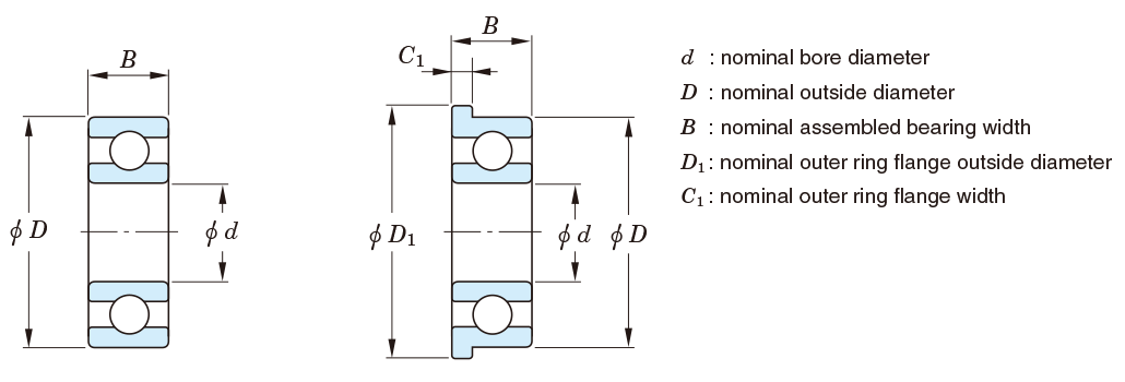
Table 7-5 Tolerances for metric series tapered roller bearings = JIS B 1514-1 =
(1) Inner ring
| Nominal bore diameter d mm | Single plane mean bore diameter deviation Δdmp | Single bore diameter deviation Δds | Single plane bore diameter variation Vdsp | Mean bore diameter variation Vdmp | Radial runout of assembled bearing inner ring Kia | perpendicularity of inner ring face with respect to the bore Sd | axial runout of assembled bearing inner ring Sia | Single inner ring width deviation ΔBs | |||||||||||||||||||||||||||||||||||
|---|---|---|---|---|---|---|---|---|---|---|---|---|---|---|---|---|---|---|---|---|---|---|---|---|---|---|---|---|---|---|---|---|---|---|---|---|---|---|---|---|---|---|---|
| classes 0, 6X | classes 6, 5 | class 4 | class 2 | class 4 | class 2 | classes 0, 6X | class 6 | class 5 | class 4 | class 2 | classes 0, 6X | class 6 | class 5 | class 4 | class 2 | classes 0,6X | class 6 | class 5 | class 4 | class 2 | class 5 | class 4 | class 2 | class 4 | class 2 | class 0 | class 6X | class 6 | classes 5, 4 | class 2 | |||||||||||||
| over | up to | upper | lower | upper | lower | upper | lower | upper | lower | upper | lower | upper | lower | max. | max. | max. | max. | max. | upper | lower | upper | lower | upper | lower | upper | lower | upper | lower | |||||||||||||||
| - | 10 | 0 | -12 | 0 | -71) | 0 | -5 | 0 | -4 | 0 | -5 | 0 | -4 | 12 | - | 5 | 4 | 2.5 | 9 | - | 5 | 4 | 1.5 | 15 | - | 5 | 3 | 2 | 7 | 3 | 1.5 | 3 | 2 | 0 | -120 | 0 | -50 | - | - | 0 | -200 | 0 | -200 |
| 10 | 18 | 0 | -12 | 0 | -7 | 0 | -5 | 0 | -4 | 0 | -5 | 0 | -4 | 12 | 7 | 5 | 4 | 2.5 | 9 | 5 | 5 | 4 | 1.5 | 15 | 7 | 5 | 3 | 2 | 7 | 3 | 1.5 | 3 | 2 | 0 | -120 | 0 | -50 | 0 | -120 | 0 | -200 | 0 | -200 |
| 18 | 30 | 0 | -12 | 0 | -8 | 0 | -6 | 0 | -4 | 0 | -6 | 0 | -4 | 12 | 8 | 6 | 5 | 2.5 | 9 | 6 | 5 | 4 | 1.5 | 18 | 8 | 5 | 3 | 2.5 | 8 | 4 | 1.5 | 4 | 2.5 | 0 | -120 | 0 | -50 | 0 | -120 | 0 | -200 | 0 | -200 |
| 30 | 50 | 0 | -12 | 0 | -10 | 0 | -8 | 0 | -5 | 0 | -8 | 0 | -5 | 12 | 10 | 8 | 6 | 3 | 9 | 8 | 5 | 5 | 2 | 20 | 10 | 6 | 4 | 2.5 | 8 | 4 | 2 | 4 | 2.5 | 0 | -120 | 0 | -50 | 0 | -120 | 0 | -240 | 0 | -240 |
| 50 | 80 | 0 | -15 | 0 | -12 | 0 | -9 | 0 | -5 | 0 | -9 | 0 | -5 | 15 | 12 | 9 | 7 | 4 | 11 | 9 | 6 | 5 | 2 | 25 | 10 | 7 | 4 | 3 | 8 | 5 | 2 | 4 | 3 | 0 | -150 | 0 | -50 | 0 | -150 | 0 | -300 | 0 | -300 |
| 80 | 120 | 0 | -20 | 0 | -15 | 0 | -10 | 0 | -6 | 0 | -10 | 0 | -6 | 20 | 15 | 11 | 8 | 5 | 15 | 11 | 8 | 5 | 2.5 | 30 | 13 | 8 | 5 | 3 | 9 | 5 | 2.5 | 5 | 3 | 0 | -200 | 0 | -50 | 0 | -200 | 0 | -400 | 0 | -400 |
| 120 | 180 | 0 | -25 | 0 | -18 | 0 | -13 | 0 | -7 | 0 | -13 | 0 | -7 | 25 | 18 | 14 | 10 | 7 | 19 | 14 | 9 | 7 | 3.5 | 35 | 18 | 11 | 6 | 4 | 10 | 6 | 3.5 | 7 | 4 | 0 | -250 | 0 | -50 | 0 | -250 | 0 | -500 | 0 | -500 |
| 180 | 250 | 0 | -30 | 0 | -22 | 0 | -15 | 0 | -8 | 0 | -15 | 0 | -8 | 30 | 22 | 17 | 11 | 7 | 23 | 16 | 11 | 8 | 4 | 50 | 20 | 13 | 8 | 5 | 11 | 7 | 5 | 8 | 5 | 0 | -300 | 0 | -50 | 0 | -300 | 0 | -600 | 0 | -600 |
| 250 | 315 | 0 | -35 | 0 | -251) | 0 | -18 | 0 | -8 | 0 | -18 | 0 | -8 | 35 | 25 | 19 | 12 | 8 | 26 | 19 | 13 | 9 | 5 | 60 | 30 | 13 | 9 | 6 | 13 | 8 | 5.5 | 9 | 6 | 0 | -350 | 0 | -50 | 0 | -350 | 0 | -700 | 0 | -700 |
| 315 | 400 | 0 | -40 | 0 | -301) | - | - | - | - | - | - | - | - | 40 | 30 | 23 | - | - | 30 | 23 | 15 | - | - | 70 | 35 | 15 | - | - | 15 | - | - | - | - | 0 | -400 | 0 | -50 | 0 | -400 | 0 | -8002) | - | - |
| 400 | 500 | 0 | -45 | 0 | -351) | - | - | - | - | - | - | - | - | 45 | 35 | 28 | - | - | 34 | 26 | 17 | - | - | 80 | 40 | 20 | - | - | 17 | - | - | - | - | 0 | -450 | 0 | -50 | 0 | -450 | 0 | -9002) | - | - |
| 500 | 630 | 0 | -60 | 0 | -401) | - | - | - | - | - | - | - | - | 60 | 40 | 35 | - | - | 40 | 30 | 20 | - | - | 90 | 50 | 25 | - | - | 20 | - | - | - | - | 0 | -500 | - | - | 0 | -500 | 0 | -11002) | - | - |
| 630 | 800 | 0 | -75 | 0 | -501) | - | - | - | - | - | - | - | - | 75 | 50 | 45 | - | - | 45 | 38 | 25 | - | - | 100 | 60 | 30 | - | - | 25 | - | - | - | - | 0 | -750 | - | - | 0 | -750 | 0 | -16002) | - | - |
| 800 | 1000 | 0 | -100 | 0 | -601) | - | - | - | - | - | - | - | - | 100 | 60 | 60 | - | - | 55 | 45 | 30 | - | - | 115 | 75 | 37 | - | - | 30 | - | - | - | - | 0 | -1000 | - | - | 0 | -1000 | 0 | -20002) | - | - |
(2-1) Outer ring
| Nominal outside diameter D mm | Single plane mean outside diameter deviation ΔDmp | Single outside diameter deviation ΔDs | Single plane outside diameter variation VDsp | Mean outside diameter variation VDmp | Radial runout of assembled bearing outer ring Kea | perpendicularity of outer ring outside surface with respect to the face SD3) | axial runout of assembled bearing outer ring Sea3) | ||||||||||||||||||||||||||
|---|---|---|---|---|---|---|---|---|---|---|---|---|---|---|---|---|---|---|---|---|---|---|---|---|---|---|---|---|---|---|---|---|---|
| classes 0, 6X | classes 6, 5 | class 4 | class 2 | class 4 | class 2 | classes 0, 6X | class 6 | class 5 | class 4 | class 2 | classes 0, 6X | class 6 | class 5 | class 4 | class 2 | classes 0,6X | class 6 | class 5 | class 4 | class 2 | class 5 | class 4 | class 2 | class 4 | class 2 | ||||||||
| over | up to | upper | lower | upper | lower | upper | lower | upper | lower | upper | lower | upper | lower | max. | max. | max. | max. | max. | |||||||||||||||
| - | 18 | 0 | -12 | 0 | -81) | 0 | -6 | 0 | -5 | 0 | -6 | 0 | -5 | 12 | - | 6 | 5 | 4 | 9 | - | 5 | 4 | 2.5 | 18 | - | 6 | 4 | 2.5 | 8 | 4 | 1.5 | 5 | 2.5 |
| 18 | 30 | 0 | -12 | 0 | -8 | 0 | -6 | 0 | -5 | 0 | -6 | 0 | -5 | 12 | 8 | 6 | 5 | 4 | 9 | 6 | 5 | 4 | 2.5 | 18 | 9 | 6 | 4 | 2.5 | 8 | 4 | 1.5 | 5 | 2.5 |
| 30 | 50 | 0 | -14 | 0 | -9 | 0 | -7 | 0 | -5 | 0 | -7 | 0 | -5 | 14 | 9 | 7 | 5 | 4 | 11 | 7 | 5 | 5 | 2.5 | 20 | 10 | 7 | 5 | 2.5 | 8 | 4 | 2 | 5 | 2.5 |
| 50 | 80 | 0 | -16 | 0 | -11 | 0 | -9 | 0 | -6 | 0 | -9 | 0 | -6 | 16 | 11 | 8 | 7 | 4 | 12 | 8 | 6 | 5 | 2.5 | 25 | 13 | 8 | 5 | 4 | 8 | 4 | 2.5 | 5 | 4 |
| 80 | 120 | 0 | -18 | 0 | -13 | 0 | -10 | 0 | -6 | 0 | -10 | 0 | -6 | 18 | 13 | 10 | 8 | 5 | 14 | 10 | 7 | 5 | 3 | 35 | 18 | 10 | 6 | 5 | 9 | 5 | 3 | 6 | 5 |
| 120 | 150 | 0 | -20 | 0 | -15 | 0 | -11 | 0 | -7 | 0 | -11 | 0 | -7 | 20 | 15 | 11 | 8 | 5 | 15 | 11 | 8 | 6 | 3.5 | 40 | 20 | 11 | 7 | 5 | 10 | 5 | 3.5 | 7 | 5 |
| 150 | 180 | 0 | -25 | 0 | -18 | 0 | -13 | 0 | -7 | 0 | -13 | 0 | -7 | 25 | 18 | 14 | 10 | 7 | 19 | 14 | 9 | 7 | 4 | 45 | 23 | 13 | 8 | 5 | 10 | 5 | 4 | 8 | 5 |
| 180 | 250 | 0 | -30 | 0 | -20 | 0 | -15 | 0 | -8 | 0 | -15 | 0 | -8 | 30 | 20 | 15 | 11 | 8 | 23 | 15 | 10 | 8 | 5 | 50 | 25 | 15 | 10 | 7 | 11 | 7 | 5 | 10 | 7 |
| 250 | 315 | 0 | -35 | 0 | -25 | 0 | -18 | 0 | -9 | 0 | -18 | 0 | -9 | 35 | 25 | 19 | 14 | 8 | 26 | 19 | 13 | 9 | 5 | 60 | 30 | 18 | 11 | 7 | 13 | 8 | 6 | 10 | 7 |
| 315 | 400 | 0 | -40 | 0 | -28 | 0 | -20 | 0 | -10 | 0 | -20 | 0 | -10 | 40 | 28 | 22 | 15 | 10 | 30 | 21 | 14 | 10 | 6 | 70 | 35 | 20 | 13 | 8 | 13 | 10 | 7 | 13 | 8 |
| 400 | 500 | 0 | -45 | 0 | -331) | - | - | - | - | - | - | - | - | 45 | 33 | 26 | - | - | 34 | 25 | 17 | - | - | 80 | 40 | 24 | - | - | 17 | - | - | - | - |
| 500 | 630 | 0 | -50 | 0 | -381) | - | - | - | - | - | - | - | - | 60 | 38 | 30 | - | - | 38 | 29 | 20 | - | - | 100 | 50 | 30 | - | - | 20 | - | - | - | - |
| 630 | 800 | 0 | -75 | 0 | -451) | - | - | - | - | - | - | - | - | 80 | 45 | 38 | - | - | 55 | 34 | 25 | - | - | 120 | 60 | 36 | - | - | 25 | - | - | - | - |
| 800 | 1000 | 0 | -100 | 0 | -601) | - | - | - | - | - | - | - | - | 100 | 60 | 50 | - | - | 75 | 45 | 30 | - | - | 140 | 75 | 43 | - | - | 30 | - | - | - | - |
| 1000 | 1250 | 0 | -125 | 0 | -801) | - | - | - | - | - | - | - | - | 130 | 75 | 65 | - | - | 90 | 56 | 38 | - | - | 160 | 85 | 52 | - | - | 38 | - | - | - | - |
| 1250 | 1600 | 0 | -160 | 0 | -1001) | - | - | - | - | - | - | - | - | 170 | 90 | 90 | - | - | 100 | 68 | 50 | - | - | 180 | 95 | 62 | - | - | 50 | - | - | - | - |
(2-2) Outer ring
| Nominal bore diameter d mm | Single outer ring width deviation ΔCs | ||||
|---|---|---|---|---|---|
| class 6X | classes 0,6,5,4,2 | ||||
| over | up to | upper | lower | upper | lower |
| - | 10 | 0 | -100 | Shall comform to the tolerance ΔBs on d of the same bearing | |
| 10 | 18 | 0 | -100 | ||
| 18 | 30 | 0 | -100 | ||
| 30 | 50 | 0 | -100 | ||
| 50 | 80 | 0 | -100 | ||
| 80 | 120 | 0 | -100 | ||
| 120 | 180 | 0 | -100 | ||
| 180 | 250 | 0 | -100 | ||
| 250 | 315 | 0 | -100 | ||
| 315 | 400 | 0 | -100 | ||
| 400 | 500 | 0 | -100 | ||
| 500 | 630 | - | - | ||
| 630 | 800 | - | - | ||
| 800 | 1000 | - | - | ||
[Notes]
1) Class 6 values are prescribed in JTEKT standards.
2) These shall be applied to bearings of tolerance class 5.
3) These shall not be applied to flanged bearings.
[Remark]Values in Italics are prescribed in JTEKT standards.
(3) Assembled bearing width and effective width
| Nominal bore diameter d mm | Actual bearing width deviation ΔTs | Actual effective inner sub-unit width deviation ΔT1s | Actual effective outer ring width deviation ΔT2s | ||||||||||||||||||||||||
|---|---|---|---|---|---|---|---|---|---|---|---|---|---|---|---|---|---|---|---|---|---|---|---|---|---|---|---|
| class 0 | class 6X | class 6 | classes 5, 4 | class 2 | class 0 | class 6X | classes 5, 4級 | class 2 | class 0 | class 6X | classes 5, 4級 | class 2 | |||||||||||||||
| over | up to | upper | lower | upper | lower | upper | lower | upper | lower | upper | lower | upper | lower | upper | lower | upper | lower | upper | lower | upper | lower | upper | lower | upper | lower | upper | lower |
| - | 10 | +200 | 0 | +100 | 0 | - | - | +200 | -200 | +200 | -200 | +100 | 0 | +50 | 0 | +100 | -100 | +100 | -100 | +100 | 0 | +50 | 0 | +100 | -100 | +100 | -100 |
| 10 | 18 | +200 | 0 | +100 | 0 | +200 | 0 | +200 | -200 | +200 | -200 | +100 | 0 | +50 | 0 | +100 | -100 | +100 | -100 | +100 | 0 | +50 | 0 | +100 | -100 | +100 | -100 |
| 18 | 30 | +200 | 0 | +100 | 0 | +200 | 0 | +200 | -200 | +200 | -200 | +100 | 0 | +50 | 0 | +100 | -100 | +100 | -100 | +100 | 0 | +50 | 0 | +100 | -100 | +100 | -100 |
| 30 | 50 | +200 | 0 | +100 | 0 | +200 | 0 | +200 | -200 | +200 | -200 | +100 | 0 | +50 | 0 | +100 | -100 | +100 | -100 | +100 | 0 | +50 | 0 | +100 | -100 | +100 | -100 |
| 50 | 80 | +200 | 0 | +100 | 0 | +200 | 0 | +200 | -200 | +200 | -200 | +100 | 0 | +50 | 0 | +100 | -100 | +100 | -100 | +100 | 0 | +50 | 0 | +100 | -100 | +100 | -100 |
| 80 | 120 | +200 | -200 | +100 | 0 | +200 | -200 | +200 | -200 | +200 | -200 | +100 | -100 | +50 | 0 | +100 | -100 | +100 | -100 | +100 | -100 | +50 | 0 | +100 | -100 | +100 | -100 |
| 120 | 180 | +350 | -250 | +150 | 0 | +350 | -250 | +350 | -250 | +200 | -250 | +150 | -150 | +50 | 0 | +150 | -150 | +100 | -100 | +200 | -100 | +100 | 0 | +200 | -100 | +100 | -150 |
| 180 | 250 | +350 | -250 | +150 | 0 | +350 | -250 | +350 | -250 | +200 | -300 | +150 | -150 | +50 | 0 | +150 | -150 | +100 | -150 | +200 | -100 | +100 | 0 | +200 | -100 | +100 | -150 |
| 250 | 315 | +350 | -250 | +200 | 0 | +350 | -250 | +350 | -250 | +200 | -300 | +150 | -150 | +100 | 0 | +150 | -150 | +100 | -150 | +200 | -100 | +100 | 0 | +200 | -100 | +100 | -150 |
| 315 | 400 | +400 | -400 | +200 | 0 | +400 | -400 | +400 | -4001) | - | - | +200 | -200 | +100 | 0 | +200 | -2001) | - | - | +200 | -200 | +100 | 0 | +200 | -2001) | - | - |
| 400 | 500 | +450 | -450 | +200 | 0 | +400 | -400 | +450 | -4501) | - | - | +225 | -225 | +100 | 0 | +225 | -2251) | - | - | +225 | -225 | +100 | 0 | +225 | -2251) | - | - |
| 500 | 630 | +500 | -500 | - | - | +500 | -500 | +500 | -5001) | - | - | - | - | - | - | - | - | - | - | - | - | - | - | - | - | - | - |
| 630 | 800 | +600 | -600 | - | - | +600 | -600 | +600 | -6001) | - | - | - | - | - | - | - | - | - | - | - | - | - | - | - | - | - | - |
| 800 | 1000 | +750 | -750 | - | - | +750 | -750 | +750 | -7501) | - | - | - | - | - | - | - | - | - | - | - | - | - | - | - | - | - | - |
[Note]1) These shall be applied to bearings of tolerance class 5.
[Remark]Values in Italics are prescribed in JTEKT standards.
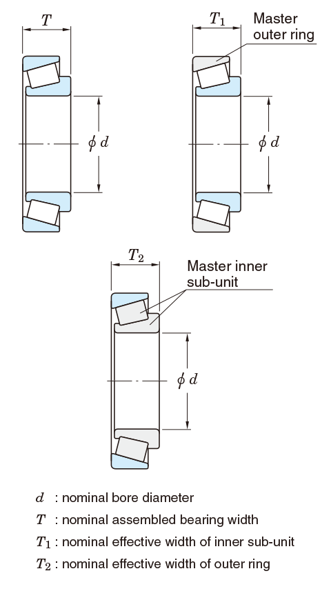
Table 7-6 Tolerances for metric series double-row and four-row tapered roller bearings (class 0) = BAS 1002 =
(1) Inner ring, outer ring width and overall width
| Nominal bore diameter d mm | Single plane mean bore diameter deviation Δdmp | Single plane bore diameter variation Vdsp | Mean bore diameter variation Vdmp | radial runout of assembled bearing inner ring Kia | Single outer ring or inner ring width deviation ΔBs , ΔCs | Actual overall inner rings/outer rings width deviation | ||||||
|---|---|---|---|---|---|---|---|---|---|---|---|---|
| Double-row Ts | Four-row ΔTs , ΔWs | |||||||||||
| over | up to | upper | lower | max. | max. | max. | upper | lower | upper | lower | upper | lower |
| 30 | 50 | 0 | -12 | 12 | 9 | 20 | 0 | -120 | +240 | -240 | - | - |
| 50 | 80 | 0 | -15 | 15 | 11 | 25 | 0 | -150 | +300 | -300 | - | - |
| 80 | 120 | 0 | -20 | 20 | 15 | 30 | 0 | -200 | +400 | -400 | +500 | -500 |
| 120 | 180 | 0 | -25 | 25 | 19 | 35 | 0 | -250 | +500 | -500 | +600 | -600 |
| 180 | 250 | 0 | -30 | 30 | 23 | 50 | 0 | -300 | +600 | -600 | +750 | -750 |
| 250 | 315 | 0 | -35 | 35 | 26 | 60 | 0 | -350 | +700 | -700 | +900 | -900 |
| 315 | 400 | 0 | -40 | 40 | 30 | 70 | 0 | -400 | +800 | -800 | +1000 | -1000 |
| 400 | 500 | 0 | -45 | 45 | 34 | 80 | 0 | -450 | +900 | -900 | +1200 | -1200 |
| 500 | 630 | 0 | -60 | 60 | 40 | 90 | 0 | -500 | +1000 | -1000 | +1200 | -1200 |
| 630 | 800 | 0 | -75 | 75 | 45 | 100 | 0 | -750 | +1500 | -1500 | - | - |
| 800 | 1000 | 0 | -100 | 100 | 55 | 115 | 0 | -1000 | +1500 | -1500 | - | - |
(2) Outer ring
| Nominal outside diameter D mm | Single plane mean outside diameter deviation ΔDmp | Single plane outside diameter variation VDsp | Mean outside diameter variation VDmp | Radial runout of assembled bearing outer ring Kea | ||
|---|---|---|---|---|---|---|
| over | up to | upper | lower | max. | max. | max. |
| 50 | 80 | 0 | -16 | 16 | 12 | 25 |
| 80 | 120 | 0 | -18 | 18 | 14 | 35 |
| 120 | 150 | 0 | -20 | 20 | 15 | 40 |
| 150 | 180 | 0 | -25 | 25 | 19 | 45 |
| 180 | 250 | 0 | -30 | 30 | 23 | 50 |
| 250 | 315 | 0 | -35 | 35 | 26 | 60 |
| 315 | 400 | 0 | -40 | 40 | 30 | 70 |
| 400 | 500 | 0 | -45 | 45 | 34 | 80 |
| 500 | 630 | 0 | -50 | 60 | 38 | 100 |
| 630 | 800 | 0 | -75 | 80 | 55 | 120 |
| 800 | 1000 | 0 | -100 | 100 | 75 | 140 |
| 1000 | 1250 | 0 | -125 | 130 | 90 | 160 |
| 1250 | 1600 | 0 | -160 | 170 | 100 | 180 |
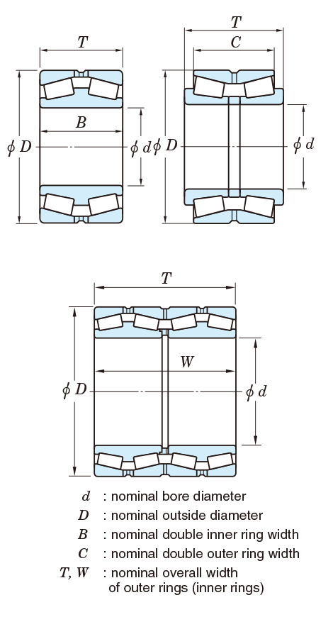
Table 7-7 Tolerances and permissible values for inch series tapered roller bearings = ANSI/ABMA 19 =
(1) Inner ring
| Applied bearing type | Nominal bore diameter d, mm(1/25.4) | Deviation of a single bore diameter Δds | ||||||||||
|---|---|---|---|---|---|---|---|---|---|---|---|---|
| Class 4 | Class 2 | Class 3 | Class 0 | Class 00 | ||||||||
| over | up to | upper | lower | upper | lower | upper | lower | upper | lower | upper | lower | |
| All types | - | 76.2(3.0) | +13 | 0 | +13 | 0 | +13 | 0 | +13 | 0 | +8 | 0 |
| 76.2(3.0) | 266.7(10.5) | +25 | 0 | +25 | 0 | +13 | 0 | +13 | 0 | +8 | 0 | |
| 266.7(10.5) | 304.8(12.0) | +25 | 0 | +25 | 0 | +13 | 0 | +13 | 0 | +8 | 0 | |
| 304.8(12.0) | 609.6(24.0) | +51 | 0 | +51 | 0 | +25 | 0 | - | - | - | - | |
| 609.6(24.0) | 914.4(36.0) | +76 | 0 | - | - | +38 | 0 | - | - | - | - | |
| 914.4(36.0) | 1219.2(48.0) | +102 | 0 | - | - | +51 | 0 | - | - | - | - | |
| 1219.2(48.0) | - | +127 | 0 | - | - | +76 | 0 | - | - | - | - | |
(2) Outer ring
| Applied bearing type | Nominal outside diameter D, mm(1/25.4) | Deviation of a single outside diameter ΔDs | ||||||||||
|---|---|---|---|---|---|---|---|---|---|---|---|---|
| Class 4 | Class 2 | Class 3 | Class 0 | Class 00 | ||||||||
| over | up to | upper | lower | upper | lower | upper | lower | upper | lower | upper | lower | |
| All types | - | 266.7(10.5) | +25 | 0 | +25 | 0 | +13 | 0 | +13 | 0 | +8 | 0 |
| 266.7(10.5) | 304.8(12.0) | +25 | 0 | +25 | 0 | +13 | 0 | +13 | 0 | +8 | 0 | |
| 304.8(12.0) | 609.6(24.0) | +51 | 0 | +51 | 0 | +25 | 0 | - | - | - | - | |
| 609.6(24.0) | 914.4(36.0) | +76 | 0 | +76 | 0 | +38 | 0 | - | - | - | - | |
| 914.4(36.0) | 1219.2(48.0) | +102 | 0 | - | - | +51 | 0 | - | - | - | - | |
| 1219.2(48.0) | - | +127 | 0 | - | - | +76 | 0 | - | - | - | - | |
(3) Radial runout of assembled bearing inner ring/outer ring
| Applied bearing type | Nominal outside diameter D, mm(1/25.4) | Radial runout of inner ring/outer ring Kia , Kea | |||||
|---|---|---|---|---|---|---|---|
| Class 4 | Class 2 | Class 3 | Class 0 | Class 00 | |||
| over | up to | max. | max. | max. | max. | max. | |
| All types | - | 266.7(10.5) | 51 | 38 | 8 | 4 | 2 |
| 266.7(10.5) | 304.8(12.0) | 51 | 38 | 8 | 4 | 2 | |
| 304.8(12.0) | 609.6(24.0) | 51 | 38 | 18 | - | - | |
| 609.6(24.0) | 914.4(36.0) | 76 | 51 | 51 | - | - | |
| 914.4(36.0) | 1219.2(48.0) | 76 | - | 76 | - | - | |
| 1219.2(48.0) | - | 76 | - | 76 | - | - | |
(4) Assembled bearing width and overall width
| Applied bearing type | Nominal bore diameter d, mm(1/25.4) | Nominal outside diameter D, mm(1/25.4) | Deviation of the actual bearing width and overall width of inner rings/outer rings ΔTs , ΔWs | |||||||||
|---|---|---|---|---|---|---|---|---|---|---|---|---|
| Class 4 | Class 2 | Class 3 | classes 0,00 | |||||||||
| over | up to | over | up to | upper | lower | upper | lower | upper | lower | upper | lower | |
| Single-row | - | 101.6(4.0) | - | - | +203 | 0 | +203 | 0 | +203 | -203 | +203 | -203 |
| 101.6(4.0) | 266.7(10.5) | +356 | -254 | +203 | 0 | +203 | -203 | +203 | -203 | |||
| 266.7(10.5) | 304.8(12.0) | - | - | +356 | -254 | +203 | 0 | +203 | -203 | +203 | -2031) | |
| 304.8(12.0) | 609.6(24.0) | - | 508.0(20.0) | - | - | +381 | -381 | +203 | -203 | - | - | |
| 304.8(12.0) | 609.6(24.0) | 508.0(20.0) | - | - | - | +381 | -381 | +381 | -381 | - | - | |
| 609.6(24.0) | - | - | +381 | -381 | - | - | +381 | -381 | - | - | ||
| Double-row | - | 101.6(4.0) | - | - | +406 | 0 | +406 | 0 | +406 | -406 | +406 | -406 |
| 101.6(4.0) | 266.7(10.5) | - | - | +711 | -508 | +406 | -203 | +406 | -406 | +406 | -406 | |
| 266.7(10.5) | 304.8(12.0) | - | - | +711 | -508 | +406 | -203 | +406 | -406 | +406 | -4061) | |
| 304.8(12.0) | 609.6(24.0) | - | 508.0(20.0) | - | - | +762 | -762 | +406 | -406 | - | - | |
| 304.8(12.0) | 609.6(24.0) | 508.0(20.0) | - | - | - | +762 | -762 | +762 | -762 | - | - | |
| 609.6(24.0) | - | - | +762 | -762 | - | - | +762 | -762 | - | - | ||
| Double-row (TNA type) |
- | 127.0(5.0) | - | - | - | - | +254 | 0 | +254 | 0 | - | - |
| 127.0(5.0) | - | - | - | - | +762 | 0 | +762 | 0 | - | - | ||
| Four-row | Total dimensional range | - | - | +1524 | -1524 | +1524 | -1524 | +1524 | -1524 | +1524 | -1524 | |
[Note]1) These shall be applied to bearings of class 0.
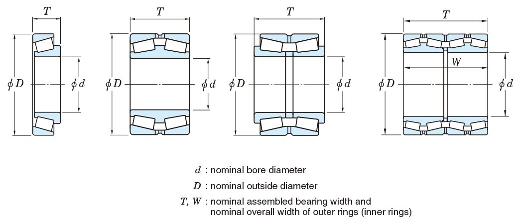
Table 7-8 Tolerances for metric J series tapered roller bearings1)
(1) Bore diameter and width of inner ring and assembled bearing width
| Nominal bore diameter d mm | Deviation of a single bore diameter Δds | Deviation of a single inner ring width ΔBs | Deviation of the actual bearing width ΔTs | ||||||||||||||||||||||
|---|---|---|---|---|---|---|---|---|---|---|---|---|---|---|---|---|---|---|---|---|---|---|---|---|---|
| Class PK | Class PN | Class PC | Class PB | Class PK | Class PN | Class PC | Class PB | Class PK | Class PN | Class PC | Class PB | ||||||||||||||
| over | up to | upper | lower | upper | lower | upper | lower | upper | lower | upper | lower | upper | lower | upper | lower | upper | lower | upper | lower | upper | lower | upper | lower | upper | lower |
| 10 | 18 | 0 | -12 | 0 | -12 | 0 | -7 | 0 | -5 | 0 | -100 | 0 | -50 | 0 | -200 | 0 | -200 | +200 | 0 | +100 | 0 | +200 | -200 | +200 | -200 |
| 18 | 30 | 0 | -12 | 0 | -12 | 0 | -8 | 0 | -6 | 0 | -100 | 0 | -50 | 0 | -200 | 0 | -200 | +200 | 0 | +100 | 0 | +200 | -200 | +200 | -200 |
| 30 | 50 | 0 | -12 | 0 | -12 | 0 | -10 | 0 | -8 | 0 | -100 | 0 | -50 | 0 | -200 | 0 | -200 | +200 | 0 | +100 | 0 | +200 | -200 | +200 | -200 |
| 50 | 80 | 0 | -15 | 0 | -15 | 0 | -12 | 0 | -9 | 0 | -150 | 0 | -50 | 0 | -300 | 0 | -300 | +200 | 0 | +100 | 0 | +200 | -200 | +200 | -200 |
| 80 | 120 | 0 | -20 | 0 | -20 | 0 | -15 | 0 | -10 | 0 | -150 | 0 | -50 | 0 | -300 | 0 | -300 | +200 | -200 | +100 | 0 | +200 | -200 | +200 | -200 |
| 120 | 180 | 0 | -25 | 0 | -25 | 0 | -18 | 0 | -13 | 0 | -200 | 0 | -50 | 0 | -300 | 0 | -300 | +350 | -250 | +150 | 0 | +350 | -250 | +200 | -250 |
| 180 | 250 | 0 | -30 | 0 | -30 | 0 | -22 | 0 | -15 | 0 | -200 | 0 | -50 | 0 | -350 | 0 | -350 | +350 | -250 | +150 | 0 | +350 | -250 | +200 | -300 |
| 250 | 315 | 0 | -35 | 0 | -35 | 0 | -22 | 0 | -15 | 0 | -200 | 0 | -50 | 0 | -350 | 0 | -350 | +350 | -250 | +200 | 0 | +350 | -300 | +200 | -300 |
(2) Outside diameter and width of outer ring and radial runout of assembled bearing inner ring/ outer ring
| Nominal outside diameter D mm | Deviation of a single outside diameter ΔDs | Deviation of a single outer ring width ΔCs | Radial runout of inner ring/outer ring Kia, Kea | ||||||||||||||||||
|---|---|---|---|---|---|---|---|---|---|---|---|---|---|---|---|---|---|---|---|---|---|
| Class PK | Class PN | Class PC | Class PB | Class PK | Class PN | Class PC | Class PB | Class PK | Class PN | Class PC | Class PB | ||||||||||
| over | up to | upper | lower | upper | lower | upper | lower | upper | lower | upper | lower | upper | lower | upper | lower | upper | lower | max. | max. | max. | max. |
| 18 | 30 | 0 | -12 | 0 | -12 | 0 | -8 | 0 | -6 | 0 | -150 | 0 | -100 | 0 | -150 | 0 | -150 | 18 | 18 | 5 | 3 |
| 30 | 50 | 0 | -14 | 0 | -14 | 0 | -9 | 0 | -7 | 0 | -150 | 0 | -100 | 0 | -150 | 0 | -150 | 20 | 20 | 6 | 3 |
| 50 | 80 | 0 | -16 | 0 | -16 | 0 | -11 | 0 | -9 | 0 | -150 | 0 | -100 | 0 | -150 | 0 | -150 | 25 | 25 | 6 | 4 |
| 80 | 120 | 0 | -18 | 0 | -18 | 0 | -13 | 0 | -10 | 0 | -200 | 0 | -100 | 0 | -200 | 0 | -200 | 35 | 35 | 6 | 4 |
| 120 | 150 | 0 | -20 | 0 | -20 | 0 | -15 | 0 | -11 | 0 | -200 | 0 | -100 | 0 | -200 | 0 | -200 | 40 | 40 | 7 | 4 |
| 150 | 180 | 0 | -25 | 0 | -25 | 0 | -18 | 0 | -13 | 0 | -200 | 0 | -100 | 0 | -250 | 0 | -250 | 45 | 45 | 8 | 4 |
| 180 | 250 | 0 | -30 | 0 | -30 | 0 | -20 | 0 | -15 | 0 | -250 | 0 | -100 | 0 | -250 | 0 | -250 | 50 | 50 | 10 | 5 |
| 250 | 315 | 0 | -35 | 0 | -35 | 0 | -25 | 0 | -18 | 0 | -250 | 0 | -100 | 0 | -300 | 0 | -300 | 60 | 60 | 11 | 5 |
| 315 | 400 | 0 | -40 | 0 | -40 | 0 | -28 | - | - | 0 | -250 | 0 | -100 | 0 | -300 | - | - | 70 | 70 | 13 | - |
[Note]1) Bearings with supplementary code "J" attached at the front of bearing number Ex. JHM720249/JHM720210, and the like
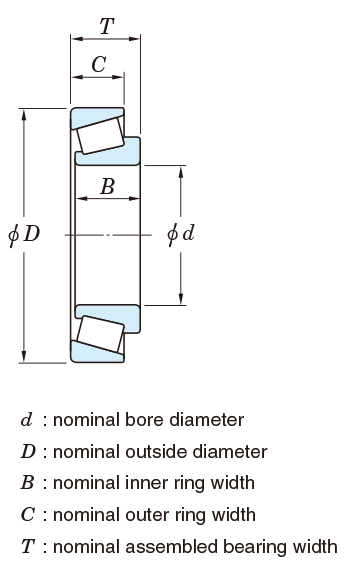
Table 7-9 Tolerances for thrust ball bearings = JIS B 1514-2 =
(1) Shaft race and central race
| Nominal bore diameter of shaft or central race d or d2,mm | Single plane mean bore diameter deviation Δdmp or Δd2mp | Single plane bore diameter variation Vdsp or Vd2sp | Race raceway to back face thickness variation Si1) 2) | ||||||||
|---|---|---|---|---|---|---|---|---|---|---|---|
| classes 0, 6, 5 | class 4 | classes 0, 6, 5 | class 4 | class 0 | class 6 | class 5 | class 4 | ||||
| over | up to | upper | lower | upper | lower | max. | max. | ||||
| - | 18 | 0 | -8 | 0 | -7 | 6 | 5 | 10 | 5 | 3 | 2 |
| 18 | 30 | 0 | -10 | 0 | -8 | 8 | 6 | 10 | 5 | 3 | 2 |
| 30 | 50 | 0 | -12 | 0 | -10 | 9 | 8 | 10 | 6 | 3 | 2 |
| 50 | 80 | 0 | -15 | 0 | -12 | 11 | 9 | 10 | 7 | 4 | 3 |
| 80 | 120 | 0 | -20 | 0 | -15 | 15 | 11 | 15 | 8 | 4 | 3 |
| 120 | 180 | 0 | -25 | 0 | -18 | 19 | 14 | 15 | 9 | 5 | 4 |
| 180 | 250 | 0 | -30 | 0 | -22 | 23 | 17 | 20 | 10 | 5 | 4 |
| 250 | 315 | 0 | -35 | 0 | -25 | 26 | 19 | 25 | 13 | 7 | 5 |
| 315 | 400 | 0 | -40 | 0 | -30 | 30 | 23 | 30 | 15 | 7 | 5 |
| 400 | 500 | 0 | -45 | 0 | -35 | 34 | 26 | 30 | 18 | 9 | 6 |
| 500 | 630 | 0 | -50 | 0 | -40 | 38 | 30 | 35 | 21 | 11 | 7 |
| 630 | 800 | 0 | -75 | 0 | -50 | 55 | 40 | 40 | 25 | 13 | 8 |
| 800 | 1000 | 0 | -100 | - | - | 75 | - | 45 | 30 | 15 | - |
| 1000 | 1250 | 0 | -125 | - | - | 95 | - | 50 | 35 | 18 | - |
[Notes]
1) Double direction thrust ball bearings shall be included in d of single direction thrust ball bearings of the same diameter series and nominal outside diameter.
2) Applies only to thrust ball bearings and cylindrical roller thrust bearings with 90° contact angle.
(2) Housing race
| Nominal outside diameter D mm | Single plane mean outside diameter deviation ΔDmp | Single plane outside diameter variation VDsp | Race raceway to back face thickness variation Se1)2) | |||||
|---|---|---|---|---|---|---|---|---|
| classes 0, 6, 5 | class 4 | classes 0, 6, 5 | class 4 | classes 0, 6, 5, 4 | ||||
| over | up to | upper | lower | upper | lower | max. | max. | |
| 10 | 18 | 0 | -11 | 0 | -7 | 8 | 5 | Shall conform to the tolerance Si on d or d2 of the same bearing |
| 18 | 30 | 0 | -13 | 0 | -8 | 10 | 6 | |
| 30 | 50 | 0 | -16 | 0 | -9 | 12 | 7 | |
| 50 | 80 | 0 | -19 | 0 | -11 | 14 | 8 | |
| 80 | 120 | 0 | -22 | 0 | -13 | 17 | 10 | |
| 120 | 180 | 0 | -25 | 0 | -15 | 19 | 11 | |
| 180 | 250 | 0 | -30 | 0 | -20 | 23 | 15 | |
| 250 | 315 | 0 | -35 | 0 | -25 | 26 | 19 | |
| 315 | 400 | 0 | -40 | 0 | -28 | 30 | 21 | |
| 400 | 500 | 0 | -45 | 0 | -33 | 34 | 25 | |
| 500 | 630 | 0 | -50 | 0 | -38 | 38 | 29 | |
| 630 | 800 | 0 | -75 | 0 | -45 | 55 | 34 | |
| 800 | 1000 | 0 | -100 | 0 | -60 | 75 | 45 | |
| 1000 | 1250 | 0 | -125 | - | - | 95 | - | |
| 1250 | 1600 | 0 | -160 | - | - | 120 | - | |
[Notes]
1) These shall be applied to race with flat back face only.
2) Applies only to thrust ball bearings and cylindrical roller thrust bearings with 90° contact angle.
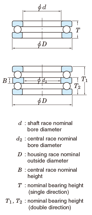
(3) Bearing height and central race height
| Nominal bore diameter d mm | Single direction | Double direction | |||||||
|---|---|---|---|---|---|---|---|---|---|
| Deviation of the actual bearing height ΔTs | Deviation of the actual bearing height ΔT1s1) | Deviation of the actual bearing height ΔT2s1) | Deviation of a single central race height B ΔBs1) | ||||||
| class 0 | class 0 | class 0 | class 0 | ||||||
| over | up to | upper | lower | upper | lower | upper | lower | upper | lower |
| - | 30 | 0 | -75 | +50 | -150 | 0 | -75 | 0 | -50 |
| 30 | 50 | 0 | -100 | +75 | -200 | 0 | -100 | 0 | -75 |
| 50 | 80 | 0 | -125 | +100 | -250 | 0 | -125 | 0 | -100 |
| 80 | 120 | 0 | -150 | +125 | -300 | 0 | -150 | 0 | -125 |
| 120 | 180 | 0 | -175 | +150 | -350 | 0 | -175 | 0 | -150 |
| 180 | 250 | 0 | -200 | +175 | -400 | 0 | -200 | 0 | -175 |
| 250 | 315 | 0 | -225 | +200 | -450 | 0 | -225 | 0 | -200 |
| 315 | 400 | 0 | -300 | +250 | -600 | 0 | -300 | 0 | -250 |
[Note]
1) Double direction thrust ball bearings shall be included in d of single direction thrust ball bearings of the same diameter series and nominal outside diameter.
[Remark]Values in Italics are prescribed in JTEKT standards.
Table 7-10 Tolerances for spherical thrust roller bearings (class 0) = JIS B 1514-2 =
(1) Shaft race
| Nominal bore diameter d mm | Single plane mean bore diameter deviation ΔDmp | Single plane bore diameter variation Vdsp | Refer. | ||||
|---|---|---|---|---|---|---|---|
| perpendicularity of inner ring face with respect to the bore Sd | Actual bearing height deviation ΔTs | ||||||
| over | up to | upper | lower | max. | max. | upper | lower |
| 50 | 80 | 0 | -15 | 11 | 25 | +150 | -150 |
| 80 | 120 | 0 | -20 | 15 | 25 | +200 | -200 |
| 120 | 180 | 0 | -25 | 19 | 30 | +250 | -250 |
| 180 | 250 | 0 | -30 | 23 | 30 | +300 | -300 |
| 250 | 315 | 0 | -35 | 26 | 35 | +350 | -350 |
| 315 | 400 | 0 | -40 | 30 | 40 | +400 | -400 |
| 400 | 500 | 0 | -45 | 34 | 45 | +450 | -450 |
[Remark]Values in Italics are prescribed in JTEKT standards.
(2) Housing race
| Nominal outside diameter D,mm | Single plane mean outside diameter deviation ΔDmp | ||
|---|---|---|---|
| over | up to | upper | lower |
| 120 | 180 | 0 | -25 |
| 180 | 250 | 0 | -30 |
| 250 | 315 | 0 | -35 |
| 315 | 400 | 0 | -40 |
| 400 | 500 | 0 | -45 |
| 500 | 630 | 0 | -50 |
| 630 | 800 | 0 | -75 |
| 800 | 1000 | 0 | -100 |
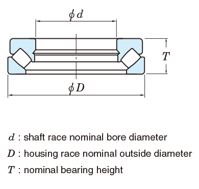
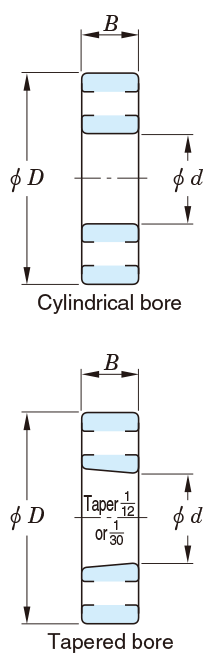
Table 7-11 Tolerances and permissible values for tapered bores of radial bearings (class 0 ⋅⋅⋅ JIS B 1514-1)
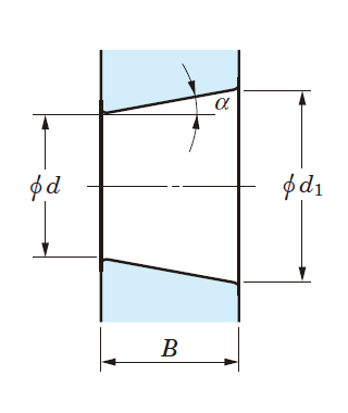
Theoretical tapered bore
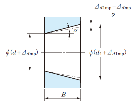
Tapered bore with single plane mean bore diameter deviation
(1) Basically tapered bore (taper 1:12)
| Nominal bore diameter d,mm | Δdmp | Δd1mp-Δdmp | Vdsp1) | |||
|---|---|---|---|---|---|---|
| over | up to | upper | lower | upper | lower | max. |
| - | 10 | +22 | 0 | +15 | 0 | 9 |
| 10 | 18 | +27 | 0 | +18 | 0 | 11 |
| 18 | 30 | +33 | 0 | +21 | 0 | 13 |
| 30 | 50 | +39 | 0 | +25 | 0 | 16 |
| 50 | 80 | +46 | 0 | +30 | 0 | 19 |
| 80 | 120 | +54 | 0 | +35 | 0 | 22 |
| 120 | 180 | +63 | 0 | +40 | 0 | 40 |
| 180 | 250 | +72 | 0 | +46 | 0 | 46 |
| 250 | 315 | +81 | 0 | +52 | 0 | 52 |
| 315 | 400 | +89 | 0 | +57 | 0 | 57 |
| 400 | 500 | +97 | 0 | +63 | 0 | 63 |
| 500 | 630 | +110 | 0 | +70 | 0 | 70 |
| 630 | 800 | +125 | 0 | +80 | 0 | - |
| 800 | 1000 | +140 | 0 | +90 | 0 | - |
| 1000 | 1250 | +165 | 0 | +105 | 0 | - |
| 1250 | 1600 | +195 | 0 | +125 | 0 | - |
(2) Basically tapered bore (taper 1:30)
| Nominal bore diameter d,mm | Δdmp | Δd1mp-Δdmp | Vdsp1) | |||
|---|---|---|---|---|---|---|
| over | up to | upper | lower | upper | lower | max. |
| - | 50 | +15 | 0 | +30 | 0 | 19 |
| 50 | 80 | +15 | 0 | +30 | 0 | 19 |
| 80 | 120 | +20 | 0 | +35 | 0 | 22 |
| 120 | 180 | +25 | 0 | +40 | 0 | 40 |
| 180 | 250 | +30 | 0 | +46 | 0 | 46 |
| 250 | 315 | +35 | 0 | +52 | 0 | 52 |
| 315 | 400 | +40 | 0 | +57 | 0 | 57 |
| 400 | 500 | +45 | 0 | +63 | 0 | 63 |
| 500 | 630 | +50 | 0 | +70 | 0 | 70 |
[Note]1) These shall be applied to all radial planes with tapered bore, not be applied to bearings of diameter series 7, 8.
[Remark]
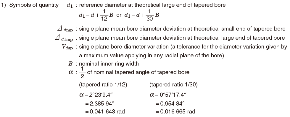
Table 7-12 Tolerances and permissible values for flanged radial ball bearings
(1) Tolerances on flange outside diameters
| Nominal outer ring flange outside diameter D1 (mm) | Deviation of single outer ring flange outside diameter,ΔD1s | ||||
|---|---|---|---|---|---|
| Locating flange | Non-locating flange | ||||
| over | up to | upper | lower | upper | lower |
| - | 6 | 0 | -36 | +220 | -36 |
| 6 | 10 | 0 | -36 | +220 | -36 |
| 10 | 18 | 0 | -43 | +270 | -43 |
| 18 | 30 | 0 | -52 | +330 | -52 |
| 30 | 50 | 0 | -62 | +390 | -62 |
| 50 | 80 | 0 | -74 | +460 | -74 |
[notice]There might be exception precision other than the above. In that case please contact JTEKT.
(2) Tolerances and permissible values on flange widths and permissible values of running accuracies relating to flanges
| Nominal outside diameter D (mm) | Deviation of single outer ring flange width ΔC1s 1) | Variation of outer ring flange width VC1s1) | Perpendicularity of outer ring outside surface with respect to the flange back face SD1 | Axial runout of assembled bearing outer ring flange back face Sea1 | ||||||||||||||
|---|---|---|---|---|---|---|---|---|---|---|---|---|---|---|---|---|---|---|
| Deep groove ball bearings and angular contact ball bearings | Tapered roller bearings | Deep groove ball bearings and angular contact ball bearings | Tapered roller bearings | |||||||||||||||
| classes 0, 6, 5, 4, 2 | classes 0, 6 | class 5 | class 4 | class 2 | class 5 | class 4 | class 2 | class 5 | class 4 | class 2 | class 5 | class 4 | class 2 | class 4 | class 2 | |||
| over | up to | upper | lower | max. | max. | max. | max. | max. | ||||||||||
| - | 2.5 | Shall conform to the tolerance ΔBs on d of the same class and the bearing | Shall conform to the tolerance VBs on d of the same class and the bearing | 5 | 2.5 | 1.5 | 8 | 4 | 1.5 | 8 | 4 | 1.5 | 11 | 7 | 3 | 7 | 4 | |
| 2.5 | 6 | 5 | 2.5 | 1.5 | 8 | 4 | 1.5 | 8 | 4 | 1.5 | 11 | 7 | 3 | 7 | 4 | |||
| 6 | 18 | 5 | 2.5 | 1.5 | 8 | 4 | 1.5 | 8 | 4 | 1.5 | 11 | 7 | 3 | 7 | 4 | |||
| 18 | 30 | 5 | 2.5 | 1.5 | 8 | 4 | 1.5 | 8 | 4 | 1.5 | 11 | 7 | 4 | 7 | 4 | |||
| 30 | 50 | 5 | 2.5 | 1.5 | 8 | 4 | 1.5 | 8 | 4 | 2 | 11 | 7 | 4 | 7 | 4 | |||
| 50 | 80 | 6 | 3 | 1.5 | 8 | 4 | 1.5 | 8 | 4 | 2.5 | 14 | 7 | 6 | 7 | 6 | |||
[Note]1) These shall be applied to groove ball bearings, i.e. deep groove ball bearing and angular contact ball bearing etc.
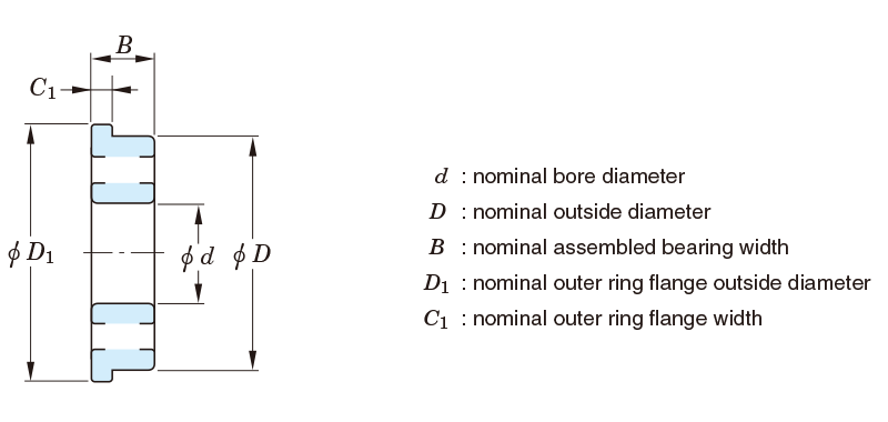
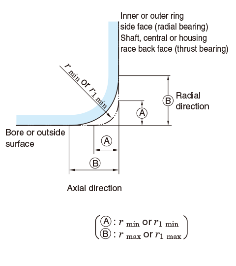
Table 7-13 Permissible values for chamfer dimensions = JIS B 1514-3 =
(1) Radial bearing (tapered roller bearings excluded)
| rmin or r1min | Nominal bore diameter d mm | rmax or r1max | ||
|---|---|---|---|---|
| over | up to | Radial direction | Axial direction | |
| 0.05 | - | - | 0.1 | 0.2 |
| 0.08 | - | - | 0.16 | 0.3 |
| 0.1 | - | - | 0.2 | 0.4 |
| 0.15 | - | - | 0.3 | 0.6 |
| 0.2 | - | - | 0.5 | 0.8 |
| 0.3 | - | 40 | 0.6 | 1 |
| 40 | - | 0.8 | 1 | |
| 0.6 | - | 40 | 1 | 2 |
| 40 | - | 1.3 | 2 | |
| 1 | - | 50 | 1.5 | 3 |
| 50 | - | 1.9 | 3 | |
| 1.1 | - | 120 | 2 | 3.5 |
| 120 | - | 2.5 | 4 | |
| 1.5 | - | 120 | 2.3 | 4 |
| 120 | - | 3 | 5 | |
| 2 | - | 80 | 3 | 4.5 |
| 80 | 220 | 3.5 | 5 | |
| 220 | - | 3.8 | 6 | |
| 2.1 | - | 280 | 4 | 6.5 |
| 280 | - | 4.5 | 7 | |
| 2.5 | - | 100 | 3.8 | 6 |
| 100 | 280 | 4.5 | 6 | |
| 280 | - | 5 | 7 | |
| 3 | - | 280 | 5 | 8 |
| 280 | - | 5.5 | 8 | |
| 4 | - | - | 6.5 | 9 |
| 5 | - | - | 8 | 10 |
| 6 | - | - | 10 | 13 |
| 7.5 | - | - | 12.5 | 17 |
| 9.5 | - | - | 15 | 19 |
| 12 | - | - | 18 | 24 |
| 15 | - | - | 21 | 30 |
| 19 | - | - | 25 | 38 |
[Remarks]
1. Value of rmax or r1 max in the axial direction of bearings with nominal width lower than 2 mm shall be the same as the value in radial direction.
2. There shall be no specification for the accuracy of the shape of the chamfer surface, but its outline in the axial plane shall not be situated outside of the imaginary circle arc with a radius of rmin or r1 min which contacts the inner ring side face and bore, or the outer ring side face and outside surface.
(2) Radial bearings with locating snap ring (snap ring groove side) and cylindrical roller bearings (separete thrust collar and loose rib side)
| r1 min | Nominal bore dia. or nominal outside dia. d or D | r1 max | ||
|---|---|---|---|---|
| over | up to | Radial direction | Axial direction | |
| 0.2 | - | - | 0.5 | 0.5 |
| 0.3 | - | 40 | 0.6 | 0.8 |
| 40 | - | 0.8 | 0.8 | |
| 0.5 | - | 40 | 1 | 1.5 |
| 40 | - | 1.3 | 1.5 | |
| 0.6 | - | 40 | 1 | 1.5 |
| 40 | - | 1.3 | 1.5 | |
| 1 | - | 50 | 1.5 | 2.2 |
| 50 | - | 1.9 | 2.2 | |
| 1.1 | - | 120 | 2 | 2.7 |
| 120 | - | 2.5 | 2.7 | |
| 1.5 | - | 120 | 2.3 | 3.5 |
| 120 | - | 3 | 3.5 | |
| 2 | - | 80 | 3 | 4 |
| 80 | 220 | 3.5 | 4 | |
| 220 | - | 3.8 | 4 | |
| 2.1 | - | 280 | 4 | 4.5 |
| 280 | - | 4.5 | 4.5 | |
| 2.5 | - | 100 | 3.8 | 5 |
| 100 | 280 | 4.5 | 5 | |
| 280 | - | 5 | 5 | |
| 3 | - | 280 | 5 | 5.5 |
| 280 | - | 5.5 | 5.5 | |
| 4 | - | - | 6.5 | 6.5 |
| 5 | - | - | 8 | 8 |
| 6 | - | - | 10 | 10 |
[Remark]
There shall be no specification for the accuracy of the shape of the chamfer surface, but its outline in the axial plane shall not be situated outside of the imaginary circle arc with a radius of r1 min which contacts the inner ring side face and bore, or the outer ring side face and outside surface.
(3) Cylindrical roller bearings (non-rib side) and angular contact ball bearings (front face side)
| r1 min | Nominal bore dia. or nominal outside dia. d or D | r1 max | ||
|---|---|---|---|---|
| over | up to | Radial direction | Axial direction | |
| 0.1 | - | - | 0.2 | 0.4 |
| 0.15 | - | - | 0.3 | 0.6 |
| 0.2 | - | - | 0.5 | 0.8 |
| 0.3 | - | 40 | 0.6 | 1 |
| 40 | - | 0.8 | 1 | |
| 0.6 | - | 40 | 1 | 2 |
| 40 | - | 1.3 | 2 | |
| 1 | - | 50 | 1.5 | 3 |
| 50 | - | 1.9 | 3 | |
| 1.1 | - | 120 | 2 | 3.5 |
| 120 | - | 2.5 | 4 | |
| 1.5 | - | 120 | 2.3 | 4 |
| 120 | - | 3 | 5 | |
| 2 | - | 80 | 3 | 4.5 |
| 80 | 220 | 3.5 | 5 | |
| 220 | - | 3.8 | 6 | |
[Remark]
There shall be no specification for the accuracy of the shape of the chamfer surface, but its outline in the axial plane shall not be situated outside of the imaginary circle arc with a radius of r1 min which contacts the inner ring side face and bore, or the outer ring side face and outside surface.
(4) Metric series tapered roller bearing
| rmin or r1 min | Nominal bore dia. or nominal outside dia.1) d or D, mm | rmax or r1 max | ||
|---|---|---|---|---|
| over | up to | Radial direction | Axial direction | |
| 0.3 | - | 40 | 0.7 | 1.4 |
| 40 | - | 0.9 | 1.6 | |
| 0.6 | - | 40 | 1.1 | 1.7 |
| 40 | - | 1.3 | 2 | |
| 1 | - | 50 | 1.6 | 2.5 |
| 50 | - | 1.9 | 3 | |
| 1.5 | - | 120 | 2.3 | 3 |
| 120 | 250 | 2.8 | 3.5 | |
| 250 | - | 3.5 | 4 | |
| 2 | - | 120 | 2.8 | 4 |
| 120 | 250 | 3.5 | 4.5 | |
| 250 | - | 4 | 5 | |
| 2.5 | - | 120 | 3.5 | 5 |
| 120 | 250 | 4 | 5.5 | |
| 250 | - | 4.5 | 6 | |
| 3 | - | 120 | 4 | 5.5 |
| 120 | 250 | 4.5 | 6.5 | |
| 250 | 400 | 5 | 7 | |
| 400 | - | 5.5 | 7.5 | |
| 4 | - | 120 | 5 | 7 |
| 120 | 250 | 5.5 | 7.5 | |
| 250 | 400 | 6 | 8 | |
| 400 | - | 6.5 | 8.5 | |
| 5 | - | 180 | 6.5 | 8 |
| 180 | - | 7.5 | 9 | |
| 6 | - | 180 | 7.5 | 10 |
| 180 | - | 9 | 11 | |
| 7.5 | - | - | 12.5 | 17 |
| 9.5 | - | - | 15 | 19 |
[Note]1) Inner ring shall be included in division d, and outer ring, in division D.
[Remarks]
1. There shall be no specification for the accuracy of the shape of the chamfer surface, but its outline in the axial plane shall not be situated outside of the imaginary circle arc with a radius of rmin or r1 min which contacts the inner ring back face and bore, or the outer ring back face and outside surface.
2. Values in Italics are provided in JTEKT standards.
(5) Thrust bearing
| rmin or r1 min | rmax or r1 max |
|---|---|
| Radial and axial direction | |
| 0.05 | 0.1 |
| 0.08 | 0.16 |
| 0.1 | 0.2 |
| 0.15 | 0.3 |
| 0.2 | 0.5 |
| 0.3 | 0.8 |
| 0.6 | 1.5 |
| 1 | 2.2 |
| 1.1 | 2.7 |
| 1.5 | 3.5 |
| 2 | 4 |
| 2.1 | 4.5 |
| 3 | 5.5 |
| 4 | 6.5 |
| 5 | 8 |
| 6 | 10 |
| 7.5 | 12.5 |
| 9.5 | 15 |
| 12 | 18 |
| 15 | 21 |
| 19 | 25 |
[Remark]
There shall be no specification for the accuracy of the shape of the chamfer surface, but its outline in the axial plane shall not be situated outside of the imaginary circle arc with a radius of rmin or r1 min which contacts with the shaft or central race back face and bore, or the housing race back face and outside surface.