For angular contact ball bearings and tapered roller bearings, the "back-to-back" arrangement is generally used to apply preload for higher rigidity.
This is because shaft rigidity is improved by the longer distance between load centers in the back-to-back arrangement.
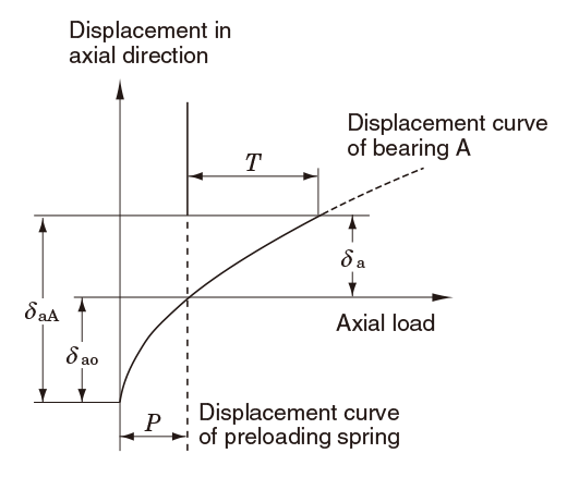
Fig. 11-1 shows the relationship between preload given via position preloading and rigidity expressed by displacement in the axial direction of the back-to-back bearing.
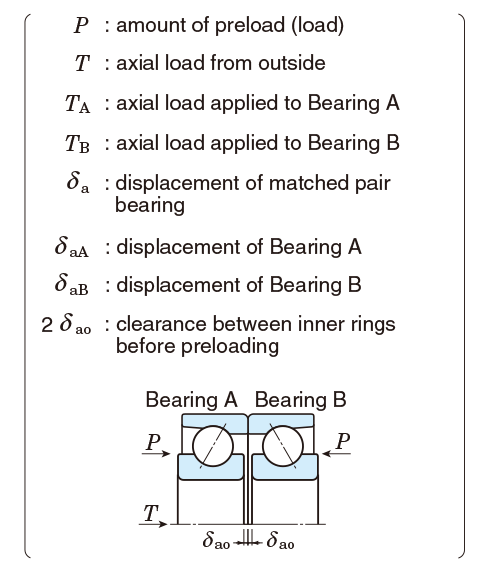
In Fig. 11-1, when preload P is applied (inner ring is tightened toward the axial direction), bearings A and B are displaced by δao respectively, and the clearance between inner rings diminishes from 2δao to zero. The displacement when axial load T is applied to these matched pair bearings from the outside can be determined as δa .
[For reference]How to determine δa in Fig. 11-1
- Determine the displacement curve of bearing A.
- Determine the displacement curve of bearing B. ...Symmetrical curve in relation to horizontal axis intersecting vertical line of preload P at point x.
- With the load from outside defined as T, determine line segment x - y on the horizontal line passing through point x.
Displace segment x - y in parallel along the displacement curve of bearing B.
Determine point y' at which to intersect displacement curve of bearing A. - δa can be determined as the distance between line segments x' − y' and x − y.
Fig. 11-2 shows the relationship between preload and rigidity in the constant pressure preloading using the same matched pair bearings as in Fig. 11-1.
In this case, since the spring rigidity can be ignored, the matched pair bearing shows almost the same rigidity as a separate bearing with preload P applied in advance.
Fig. 11-1 Preloading diagram in position preloading
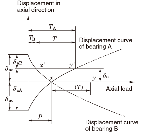
Fig. 11-2 Preloading diagram in constant pressure preloading