Loads affecting bearings includes force exerted by the weight of the object the bearings support, transmission force of devices such as gears and belts, loads generated in equipment during operation etc.
Seldom can these kinds of load be determined by simple calculation, because the load is not always constant.
In many cases, the load fluctuates, and it is difficult to determine the frequency and magnitude of the fluctuation.
Therefore, loads are normally obtained by multiplying theoretical values with various coefficients obtained empirically.
5-3-1 Load coefficient
Even if radial and axial loads are obtained through general dynamic calculation, the actual load becomes greater than the calculated value due to vibration and impact during operation.
In many cases, the load is obtained by multiplying theoretical values by the load coefficient.
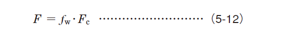
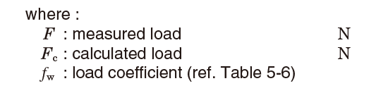
Table 5-6 Values of load coefficient ƒw
| Operating condition | Application example | ƒw |
|---|---|---|
| Operation with little vibration or impact | Motors | 1.0~1.2 |
| Machine tools | ||
| Measuring instrument | ||
| Normal operation (slight impact) |
Railway rolling stock | 1.2~2.0 |
| Automobiles | ||
| Paper manufacturing equipment | ||
| Air blowers | ||
| Compressors | ||
| Agricultural equipment | ||
| Operation with severe vibration or impact | Rolling mills | 2.0~3.0 |
| Crushers | ||
| Construction equipment | ||
| Shaker screens |
5-3-2 Load generated through belt or chain transmission
In the case of belt transmission, the theoretical value of the load affecting the pulley shafts can be determined by obtaining the effective transmission force of the belt.
For actual operation, the load is obtained by multiplying this effective transmission force by the load coefficient (ƒw) considering vibration and impact generated during operation, and the belt coefficient (ƒb) considering belt tension.
In the case of chain transmission, the load is determined using a coefficient equivalent to the belt coefficient.
This equation (5-13) is as follows ;
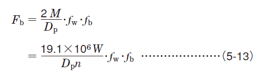
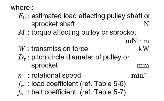
Table 5-7 Values of belt coefficient ƒb
| Belt type | ƒb |
|---|---|
| Timing belt (with teeth) | 1.3~2.0 |
| V-belt | 2.0~2.5 |
| Flat belt (with tension pulley) | 2.5~3.0 |
| Flat belt | 4.0~5.0 |
| Chain | 1.2~1.5 |
5-3-3 Load generated under gear transmission
(1) Loads affecting gear and gear coefficient
In the case of gear transmission, loads transmitted by gearing are theoretically classified into three types: tangential load (Kt), radial load (Kr) and axial load (em>Ka).
Those loads can be calculated dynamically (using equations  , em class="textImg">
 and
and  , described in section (2)).
To determine the actual gear loads, these theoretical loads must be multiplied by coefficients considering vibration and impact during operation (ƒw) (ref. Table 5-6) and the gear coefficient (ƒg) (ref. Table 5-8) considering the finish treatment of gears.
Table 5-8 Values of gear coefficient ƒg
| Gear type | ƒg |
|---|---|
| Precision gears (both pitch error and tooth shape error less than 0.02 mm) | 1.0~1.1 |
| Normal gears (both pitch error and tooth shape error less than 0.1 mm) | 1.1~1.3 |
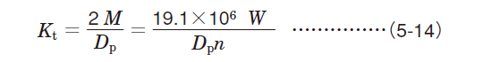
(2) Calculation of load on gears
 Tangential load (tangential force) Kt Tangential load (tangential force) Kt |
|---|
(Spur gears, helical gears, double-helical gears, straight bevel gears, spiral bevel gears)
 |
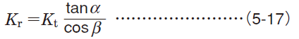
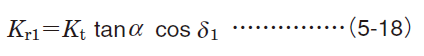
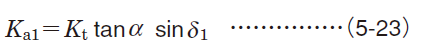
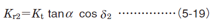
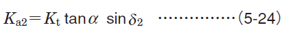
 Radial load (separating force) Kr Radial load (separating force) Kr |  Axial load (axial force) Ka Axial load (axial force) Ka | ||
|---|---|---|---|
| Spur gears |
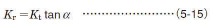 |
0 | |
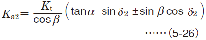
| Helical gears |
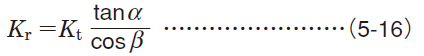 |
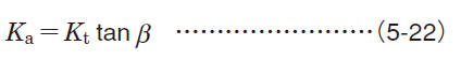 |
|
| Double-helical gears |
 |
0 | |
| Straight bevel gears1) | Drive side |
 |
 |
| Driven side |
 |
 |
|
| Spiral bevel gears1,2) | Drive side |
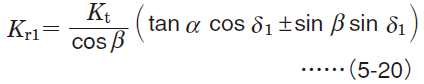 |
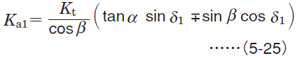 |
| Driven side |
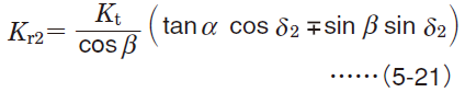 |
 |
|
[Notes]
1) Codes with subscript 1 and 2 shown in equations are respectively applicable to drive side gears and driven side gears.
2) Symbols (+) and (−) denote the following ;
Symbols in upper row : clockwise rotation accompanied by right-handed spiral or counterclockwise rotation with left-handed spiral
Symbols in lower row : counterclockwise rotation with right-handed spiral or clockwise rotation with left-handed spiral
[Remark] Rotating directions are described as viewed at the back of the apex of the pitch angle.
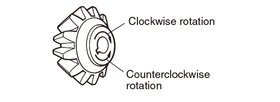
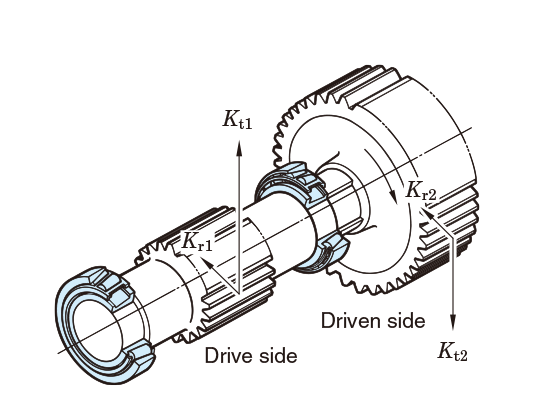
Fig. 5-7 Load on spur gears
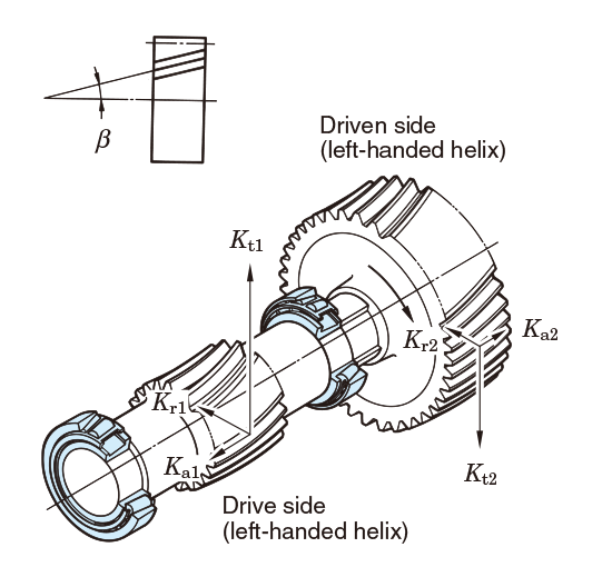
Fig. 5-8 Load on helical gears
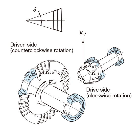
Fig. 5-9 Load on straight bevel gears
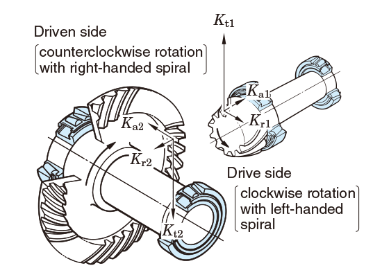
Fig. 5-10 Load on spiral bevel gears
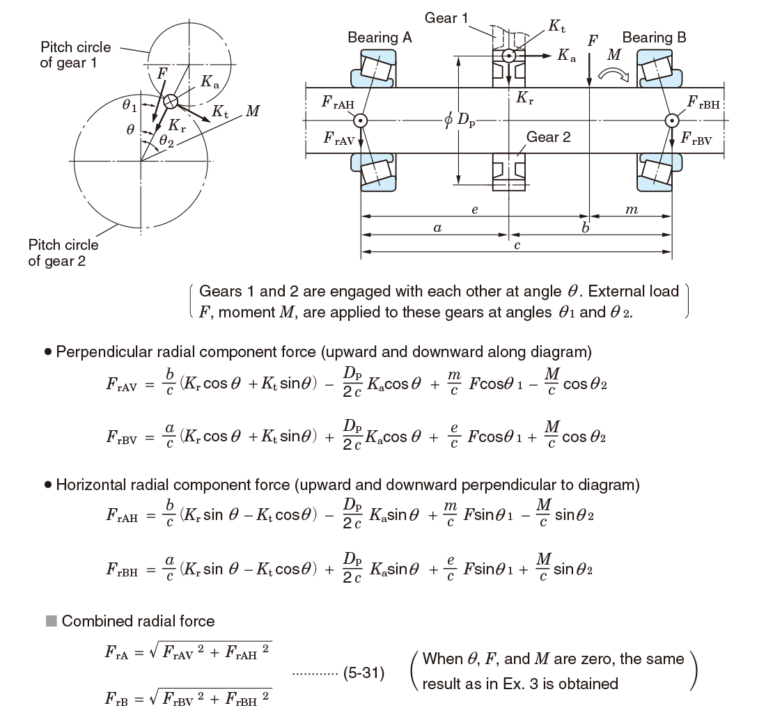
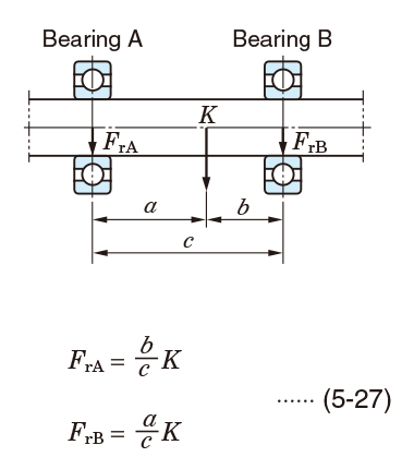
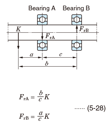
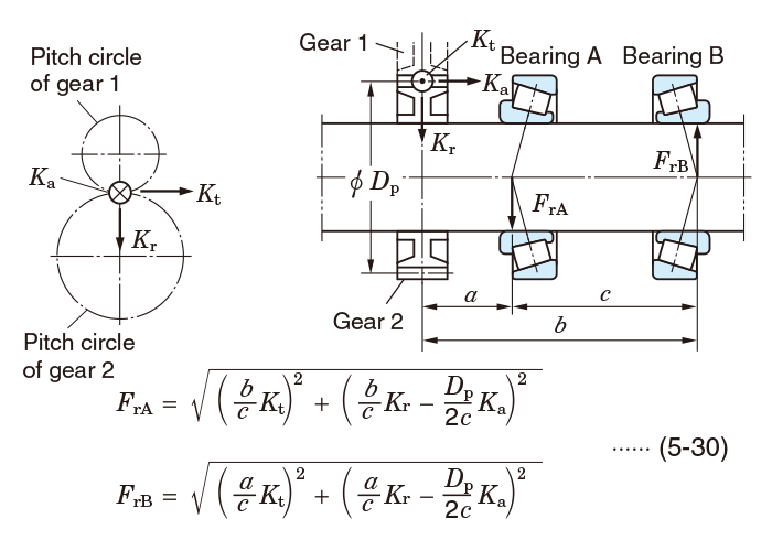
5-3-4 Load distribution on bearings
The load distribution affecting bearings can be calculated as follows: first, radial force components are calculated, then, the sum of vectors of the components is obtained in accordance with the load direction.
Calculation examples of radial load distribution are described in the following section.
[Remark]
Bearings shown in Exs. 3 to 5 are affected by components of axial force when these bearings accommodate radial load, and axial load (Ka) which is transferred externally, i.e. from gears.
For calculation of the axial load in this case, refer to page Dynamic equivalent load.
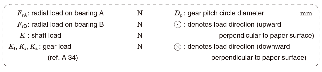
Description of signs in Examples 1 to 5
Example 1 Fundamental calculation (1)
Example 2 Fundamental calculation (2)
Example 3 Gear load distribution (1)
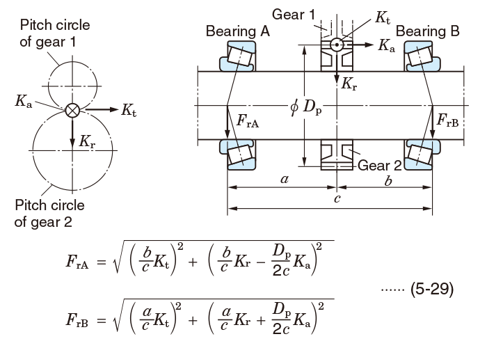
Example 4 Gear load distribution (2)
Example 5 Simultaneous application of gear load and other load