In designing the shaft and housing, the following should be taken into consideration.
- Shafts should be thick and short.
(in order to reduce distortion including bending) - Housings should possess sufficient rigidity.
(in order to reduce distortion caused by load)
[Note]
For light alloy housings, rigidity may be provided by inserting a steel bushing.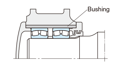
Fig. 14-1 Example of light alloy housing
- The fitting surface of the shaft and housing should be finished in order to acquire the required accuracy and roughness.
The shoulder end-face should be finished in order to be perpendicular to the shaft center or housing bore surface. (refer to Table 14-1 Recommended accuracy and roughness of shafts and housings) - The fillet radius (ra) should be smaller than chamfer dimension of the bearing.
(refer to Table 14-2 Shaft/housing fillet radius and shoulder height of radial bearings)
(refer to Table 14-3 Grinding undercut dimensions for ground shafts)
[Notes]
Generally it should be finished so as to form a simple circular arc.(refer to Fig. 14-2)
When the shaft is given a ground finish, a recess may be provided.(Fig. 14-3)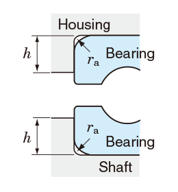
Fig. 14-2 Fillet radius
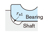
Fig. 14-3 Grinding undercut
- The shoulder height (h) should be smaller than the outside diameter of inner ring and larger than bore diameter of outer ring so that the bearing is easily dismounted.
(refer to Fig. 14-2 and Table 14-2) - If the fillet radius must be larger than the bearing chamfer, or if the shaft/housing shoulder must be low/high, insert a spacer between the inner ring and shaft shoulder as shown in Fig. 14-4, or between the outer ring and the housing shoulder.
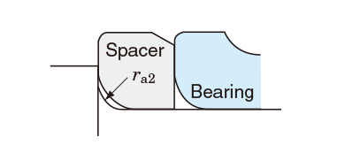
Fig. 14-4 Example of shaft with spacer
- Screw threads and lock nuts should be completely perpendicular to shaft axis. It is desirable that the tightening direction of threads and lock nuts be opposite to the shaft rotating direction.
- When split housings are used, the surfaces where the housings meet should be finished smoothly and provided with a recess at the inner ends of the surfaces that meet.
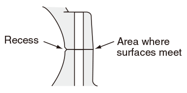
Fig. 14-5 Recesses on meeting surfaces